R Reynolds
-
Posts
176 -
Joined
-
Last visited
-
Days Won
47
Content Type
Profiles
Forums
Events
Everything posted by R Reynolds
-
So I do a test render of my new steam locomotive and I notice that something funky is happening on the half inch plate under the cab in the shadows (see image). The patch layout for that plate is legal and all the normals are pointing outward. When I built it, I was trying for the fewest patches possible. I took another swing at it without any regard for patch count and came up with something equivalent with only two more patches and a much nicer render. The only real differences are that on the offending plate there are three point patches and the three patches forming the rectangular edges of the central cutout are formed with four, dead end, two cp splines joining the two faces while on the improved plate they are made by continuing the face splines around the edge. Perhaps the moral of the story is never use dead end splines but has anyone else had a similar problem and the patience to figure out if they cause the granularity?

-
Thanks for the render Stian. I always seem to have an "out-of-model" experience when I see something I built in a render I didn't generate. Something of the order of "Did I build that?". Weird, I know. On a side note, not everyone is nostalgic about old Beetle's and buses; a not so fond look at old VW's
-
Fair warning. This was a model made before AO which is unforgiving of certain uses of hooks and neighbouring normals not all pointing in the same direction; sins which run rampant through the bus. I did a render of the bus with AO and it's pretty smudgey. I'm currently running through the bus's 10k+ patches trying to bring it up to date.
-
Actually, I built that as a favor to Greg. And I'd like to think it can hold it's own against Stian's finely crafted model. In my opinion, the weakest link in the attached render (from April 2000) is the lighting. I may have to try a new one with AO.
-
As the others have said, you need a bigger reference picture. Fortunately you've chosen to model a Pennsylvania Railroad GG1, one of the most obsessed over electric locomotives. So there's LOTS of pictures of it in 3/4 views but as usual with big vehicles, very few orthogonal views showing the whole thing. I can offer the attached four images whose lengths are all larger than the one you have. I think you'll be happy with GG1_b.gif which is a pretty large line drawing. I also threw in a picture of the chassis and trucks that I stumbled across during the search.
-
When I contributed that boxcar chassis I only had a faint hope that somebody would actually use it. Well done and thanks! Hey, I have no problem with graffiti as long as it has enough detail.
-
Is this the look you're after? http://www.hash.com/forums/index.php?showt...1&hl=bottle
-
It appears from your example scene that you're trying to simulate sunlight which is basically a single, extremely distant area light source. I have been able to satisfy my needs with a 208 ft. diameter klieg with the properties shown in the attachment, located almost 3.5 miles from the models. I also use ambiance occlusion to fill in the shadows with sky light but that may not be the look you're after.
-
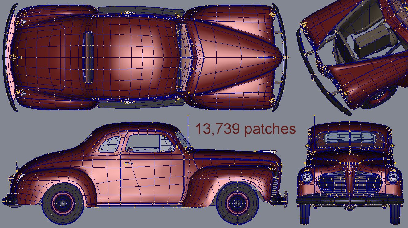
Thanks to everyone for their encouraging words. robcat asked: Your question sent me on a web search that yielded "a device for transmitting motion for some specific purpose". I always thought of a gear as a multi-armed lever or a lever as a single toothed gear, both transmit force about a rotating axis. John asked: I used to; went so far as to build a 1/48 scale set-up in the backyard so I could use natural sunlight to photograph them with a second hand 16mm movie camera. But 1/4" to the foot scale still wasn't really large enough to make the movies convincing. Then I discovered A:M and realized I could get the camera as close as I wanted and still maintain focus. The backyard set was soon dismantled. jason asked: Usually I'm OK with sharing my models but this one's going to be my pride and joy. As an alternative I can offer a hi-res view of all parts in wireframe. If there's any specific section you'd like to see more closely, just ask.
-
As the title says, this is the linkage used by steam locomotives to allow them to move forward or in reverse. The idea of splining the convoluted shapes and transitions intimidated me so much that I kept putting off starting them for months. But I finally bit the bullet and I think they can stand up to an arm's length inspection. The quasi rectangular frame (which is about 6 ft. long) has a close approximation of the final cast iron texture for all the parts but the Playdough colours on the other parts are just to ease inspection.
-
These are the quirks you have to get used to when attempting accurate mechanical modeling with A:M's splines. I have this vague memory from the last century that Hash splines did not originally act this way but due to complaints from character modelers concerning their difficulties of modeling faces without creasing that the spline algorithm was changed to include averaging over local cp's. I know all too well the temptation to concentrate on one local feature (a nicely hemmed sheet metal edge for instance) making it "perfect" and then moving on thinking it's finished, forever. But you really don't want to tweak bias until you have a significant chunk of the object built. And you'll just have to get used to re-tweaking splines after you do a C/F/A. I've noticed that typically the sign of some alpha's get flipped after that operation in an unpredictable way. After the C/F/A, put your model in wire frame and look through it for splines that don't match. Click on the badly aimed spline and change the sign of its alpha; + to - or - to +. This works most of the time but as I say it's unpredictable. Once you're mentally prepared for this added task; it's easier to swallow. As for nice shiny paint, I'd suggest a specular colour closer to white, low specular size (5?), high specular intensity (90?) and higher reflectivity (40?). Make sure you use a number of lights and surround your model with a background so there's something to reflect.
-
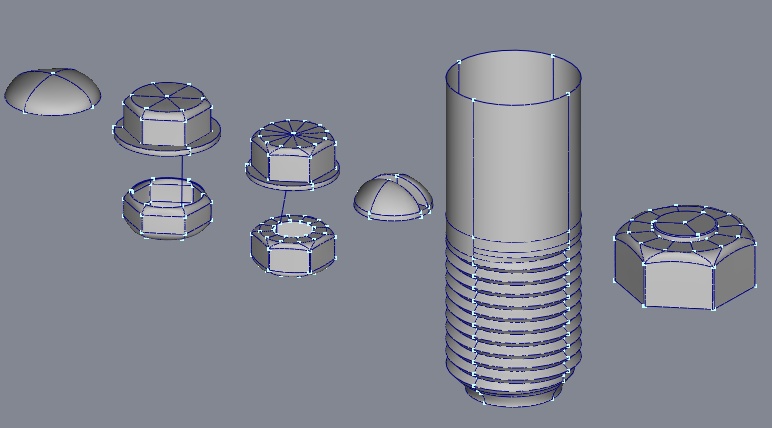
Various connectors (rivet head, slot head screw, hex head bolt & nut, partially threaded rod) for detailing mechanical models. Most use as few patches as possible, except for a hi-res version of the hex hardware which should withstand arm's length scrutiny. connector_hardware.mdl
-
I have a model file of various connector hardware that I use regularly. I try to keep patch count low so you can add a lot of them to a model. The hex head bolts and nuts come in low and hi patch counts depending upon how much scrutiny they'll come under. If this looks useful, I can upload it to this thread.
-
Thanks Eric. It does help because it confirms one my strongly held beliefs; if you start with the assumption that you're going to add as many splines as needed to fillet every corner you have nothing to fear from five pointers.
-
First rate craftsmanship Eric! May I please see a close-up wireframe of one of the wheel spokes showing the transitions into the hub and rim? I'm resplining my locomotive wheels and I'd appreciate seeing your solution.
-
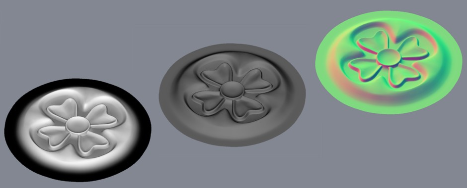
Nothing magical. A bump map comes from applying a simple gradient material that sets the color of the top of the model to (255, 255, 255), the bottom to (0, 0, 0) with a smooth transition between. Make sure you set the model's specular color to (0, 0, 0) as well. A render of a top view of such a model yields a decal where height is proportional to gray value (see attached image). As a side note, in the case of the rosette model which is a raised detail, if you applied a gradient that set the top of the model to (255, 255, 255) and the bottom of the model to (128, 128, 128) you would now have a map suitable for a displacement decal (if you can afford the render hit). The normal map is a simple application of aaver's MakeNormalMap material. found here. The only limitation being that you should test how the map renders to make sure it's default settings provide the expected results. It may be due to whatever interpolation is happening in the translation from decal to apparent surface grey value but it may also be due to the fact that I modelled some of the contours too sharp. Bump, normal and displacement maps don't play well with steep slopes i.e. rapid changes in height. They prefer rolling hills as opposed to cliffs. So I slightly blurred both maps before applying them, creating the softer edges.
-
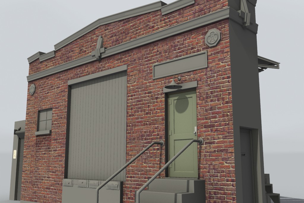
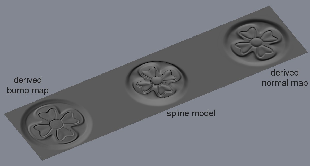
I use normal maps to cheat details that don't need to stand up to arms length inspection, so there's no need to carry the overhead of those patches. Bump maps are for textures that are so small with respect to the overall surface they essentially have no depth. For instance, the cast concrete, octogonal rosettes on either side of the front wall of building I'm working on (shown in the attached WIP image) are normal maps derived from a 600 patch model. They're so far away from the viewer that it's unlikely you'll notice they have no real depth. The second image shows an angled view comparison of the original rosette model next to applied bump and normal maps (both set at 100%) that were derived from the model. IMO the normal map (although not nearly as good as the model) is far more convincing than the bump map.
-
Here's the method I typically use to cut holes in convoluted surfaces. The steps are keyed to the attached screen grabs. 1. Cleverly lay out the splinage in your target surface with the foreknowledge of where your going to cut the hole. In this case a cylinder with enough radial and vertical cps to keep the required five point patches as small and symmetrical as possible. 2. Draw the outline cross section of the hole you want to cut using cp's that only coincide with existing splines on the target surface. 3. Move the hole's cross section cps so they all lay in the target surface. Tweak the appropriate mags and bias so its' splines also lay in the target surface. 4. Add extra cps to the splines in the target surface to match those in the cross section. Adding cp's to the circumferential spline will naturallly cause distortions that need bias correction. 5. Stitch the cross section to the cylinder. 6. Remove splines and define the five point patches. The spline ends on the broken circumferential will need bias tweaks. Are the results boolean perfect? No. You'd need to increase the spline density to further reduce the size of the five pointers to eliminate the slight distortion near the edge. However you're likely to add edge moulding that will distract the eye of the beholder.
-
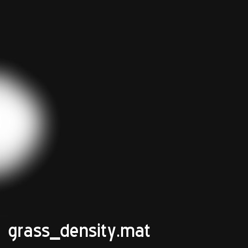
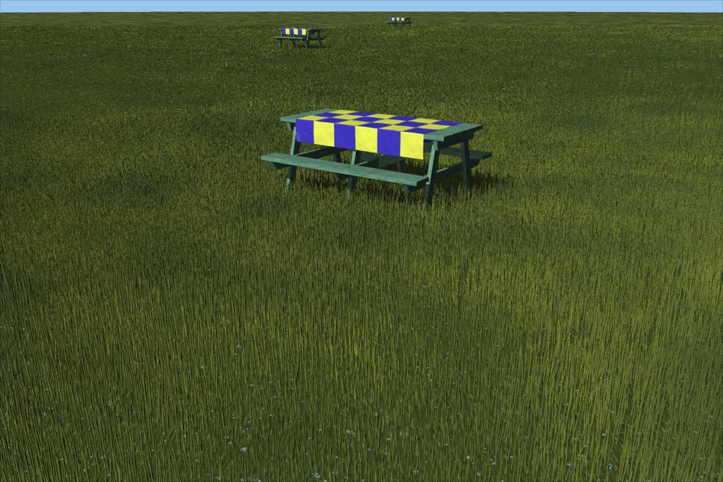
If I must, OK here goes. Keep in mind that it's been almost three years since I did this research so I don't remember every parameter setting but I can give you the broad strokes. The first thing I discovered was that rendering a landscape of grass/hair takes a long, long time, at least on a 1.5 Mhz Athlon. So I spent a fair bit of time trying to determine the minimum number of blades required to closely suggest grass as opposed to trying to accurately simulate every blade. On a model railroad, the stars are the locomotives and rolling stock not the scenery. My first "trick" was the material I applied to the ground, grass.mat, shown in the first image. This suitably noisy "quasi-grass" has blobs of contrasting color to suggest small discrete plants and really helps fill in the gaps between individual grass blades. The second trick was to use AM materials to produce images that can be used as maps to control blade color, length and density. The final trick was to realize that the grass texture you need in the foreground can be far different than what you can use in the background. The next three images are reduced versions of the maps used in the image of the hand-car and shed. The length and color maps are made with three different materials with gradient fades between them. The leftmost parts of the maps are close to the camera's possible locations while their rightmost parts will be in the distance, well in the background of the image. As you can see, I want more granularity, in both height and color, close to the camera to suggest more detail. My most surprising discovery was how little density I needed in the background and stiil have believable grass. So the density map basically concentrates grass closer to the camera. On the tall grass I seem to recall using the grooming tool to bend various sections of blades in realistic directions. The last image is an earlier test render I stumbled across while trying to refresh my memory on this process. It's closer to the original request for a lawn like landscape and uses similar maps to those attached. The repeated picnic table is just to give a sense of scale and distance.
-
The grass on the background hill was my first presentable attempt. More a field than a lawn.
-
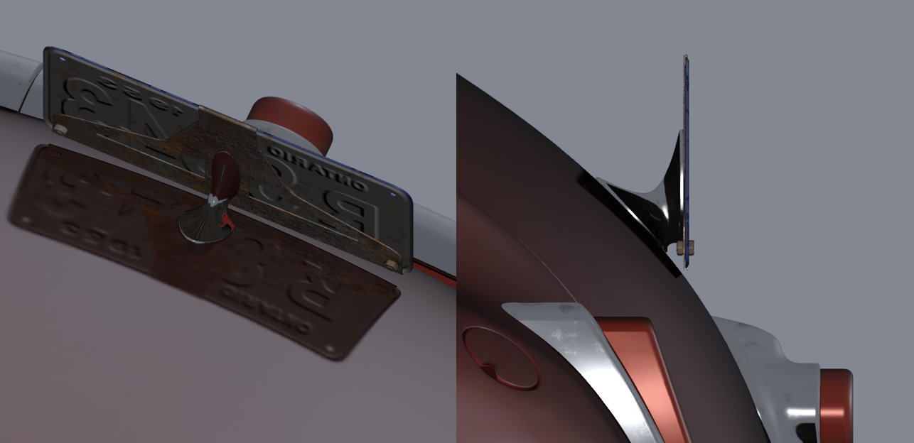
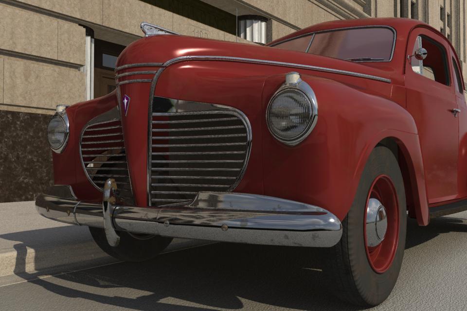
Thanks for all the kind comments. See the attached image. The biggest challenge here was I had no reference image for how the plate gets held in that odd location. So I had to design a kind of aerodynamic art-deco chunk of chrome with a rusty metal frame; see other attached image. All in good time. You're absolutely correct and I did consider it. But some rough calculations suggested that you'd have to have something like 36 radial cross sections to have a moving bulge as the wheel rotated that didn't "pulse" from cross-section to cross section and it would probably still be a bias tweaking nightmare to get it to look realistic in motion. I couldn't justify this type of patch overhead on just a car. The "stars" of my virtual train set are the locomotives. They'll get the majority of close-ups and fortunately their wheels don't deform (much). I'd like to finish the city street set first so there's something to fill in the reflections. As you can see in the view without a the hood, I did model it, along with the radiator. They're very low on detail, just enough to fill the space in a worm's eye view. The Chrysler designers put a LOT of sheet metal in front of the radiator giving that see-through appearance. My ISP puts a 5Mb limit on my website and I plan on putting many more images up in the coming years.
-
It's been about four years since I started it and I'm still tweaking the materials but it's done, finally. Three other shots, including the interior, are here: '41 Plymouth Coupe page
-
My experience has been that it's the signs of the bias values "automatically" flipping and hence being incorrect for the new orientation. As far back as the 90's, this has been the case. You will also notice that it happens when you tweak one half of a model and then copy, flip and attach. After attaching, sometimes the copied bias have the correct signs and the originals flip. It doesn't happen to every bias so you just have to prepare yourself to patiently inspect your wireframe and make sure all the bias values match. You can avoid it if you model with such high density patches that all bias values stay 0.0 but this would likely be even more tedious than checking for flipped bias signs. Since it's been around so long I assume it's a feature that's unlikley to change.
-
You may find a workable modelling solution to your problem here: Fillet Tutorial
-
"Good" is a matter of taste. Do you mean buildings like this?