R Reynolds
-
Posts
176 -
Joined
-
Last visited
-
Days Won
47
Content Type
Profiles
Forums
Events
Everything posted by R Reynolds
-
In cases such as this, my suggestion for a bias handle "lock" would be to have the ability to force a handle to always point at a selected, adjacent CP.
-

Door dents in auto sheet metal
R Reynolds replied to R Reynolds's topic in Work In Progress / Sweatbox
Yeah, that had me puzzled for a while until I happened to be watching a movie from the 40's where the hero was driving a car with similarly styled fenders. As soon as he opened the door, it was obvious (see attached reference images). The sheet metal added to the door to continue the fender shape is slightly smaller than the fender itself, so as the door opens, one shape fits inside the other. Its a clever design trick helped by the shape and location of the joint with respect to the hinge points. It's this kind of totally gratuitous design cue (like those monstrous chrome bumpers) that IMHO gives these cars so much more character than what we drive today. Very few would be willing the pay for such wasteful details.
-
Door dents in auto sheet metal
R Reynolds replied to R Reynolds's topic in Work In Progress / Sweatbox
Dings, dents, dirt and now, bird droppings...and with that final abuse, sedan_Checker_cab_48.mdl is done.
-
Door dents in auto sheet metal
R Reynolds replied to R Reynolds's topic in Work In Progress / Sweatbox
I agree with you Matt, the proportions didn't look quite right so I increased the tire width by 1 in. (25mm). The final dents are subtle but noticeable. Still working on my dirt painting technique but I'm pretty close to finished.
-
Door dents in auto sheet metal
R Reynolds replied to R Reynolds's topic in Work In Progress / Sweatbox
Experimenting with different sizes, shapes and severities. You can get away with relatively lo-res decals. The round symmetric dent is only 128 x 128. The two large ones are the same 256 x 256 decal but this is a fairly large surface feature to cheat with a decal and I'm not convinced it could withstand prolonged scrutiny up-close. But for junkers in the background, it's more than adequate. My next step is to follow Robert's suggestion to scratch the paint within the dent. This is going to take some finessing, the proof of which is illustrated at the lower left corner of the passenger door sign. In this area there are two identical dent stamps. One is centered right on that sign corner while roughly halfway between this and the driver's door gap is the second stamp. The lack of distortion in the sign makes that dent look less severe. Any scratch and rust detail are going to have to be subtle.
-
You say that as though extrusions are the only possible way to model corners with large radii. I find your lack of faith (in my model) disturbing. Beautiful woodworking by the way.
-
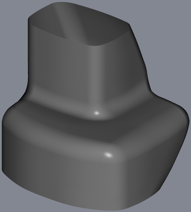
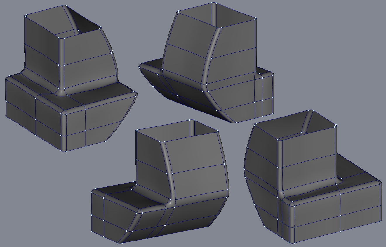
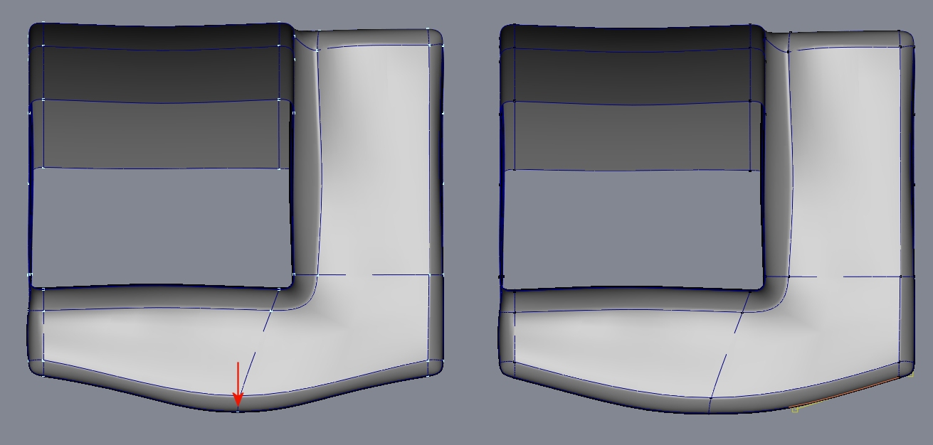
You asked for it; four views and the model itself. To me, it's not an "either/or" choice; accurate beveling (or filleting) still demands bias adjustment. I used your roto images without doing any more research into the actual shape of the bow. Based on those, it looked like there were a number of corners at the arrow rest and to me that means rounded edges. To meet my expectations of what a rounded edge should look like, it gets defined with two CPs. The model still needs a ton of bias tweaking to get all the surfaces shaped correctly. And as shown in the second image, if you want to put a curve in the front of the model by moving the CPs forward along the red arrow, you can only get a nice arc by biasing the CPs at the either end. I'd guess 95% of the times I've tried to reduce patch count (and my labour) by using just bias values to define a corner, I've been dissatisfied with the final realism of the model. Broadly speaking, every object I've wanted to accurately model can be subdivided into features that must be defined by CPs at their beginning and end. Any corner of any size, that isn't razor sharp, is just another feature. bow_test.mdl
-
First, a real question: Mark, what are you using for those marvelous brick materials/textures? Second; useless movie trivia: Played by Ross Bagdasarian who went on to fame and fortune creating "Alvin and the Chipmunks".
-
I totally understand; "give a man a fish ... teach him to fish ..." and all that. Having said that, this looked like an interesting modeling exercise so I took a crack at filling in the centre section of the previous model. I'd be happy to post the results. It's your call. (hint: Using 12 CPs, at least in the lower section, pays dividends.)
-
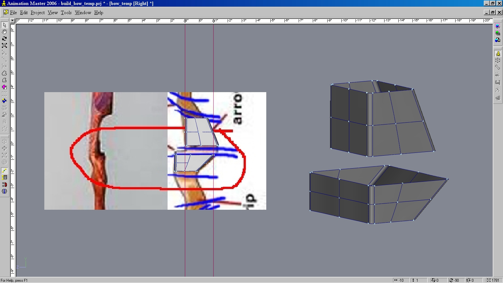
The hardest part is going to be around the arrow rest so start there, the rest will be simple shaping. That's probably true but I'd suggest you start with 12 as shown in the image. Once you're satisfied with the model you can either delete the side splines, if you decide it doesn't need them, or you can terminate them as hooks once you're into the simpler cross sections.
-
Door dents in auto sheet metal
R Reynolds replied to R Reynolds's topic in Work In Progress / Sweatbox
You certainly have a right to your opinion Matt but I disagree. The diffuse reflections in the windows (which I find totally unrealistic for typical smooth glass) come from an unexpected change in the way A:M interprets the specular size property (at least in v13). I was always under the impression that specular size was totally divorced from the actual surface properties. You could have a smooth chromed sphere with sharp reflections from the surroundings but still have a specular size of 95. Totally unrealistic but it's only a simulation of the light source's reflection. But now it seems that the specular size is increased by adding roughness to the surface. Perfectly reasonable and accurate. However for some reason I can't get specular reflections for sizes less than 0.501; specular simple disappears from 0.500 on down. Sounds like a float value is getting assigned to an integer. So to get a specular highlight I need to give glass some surface roughness. The image shows progressive renders of the taxis' rear passenger window with specular = 0 and 0.501. The roughness causes pebbly reflections of far away objects. Until I make the transition to a new computer and v16, I'll probably live with glass with no specular and realistic reflections.
-
Door dents in auto sheet metal
R Reynolds replied to R Reynolds's topic in Work In Progress / Sweatbox
Quite possibly. It's the only reason I model anything. Believe it or not my WIP model for Penn Station created the need for the taxi. The first image shows the doors to the below street level entrance. I figured it would be more convincing to have a car parked outside so dropped in my '41 Plymouth coupe. The second image was OK but I guessed a taxi would be more likely. No problem! I can find some reference images of taxis, cannibalize and reshape parts from the Plymouth and I'll have a quick & simple taxi for outside the doors. Two years later I'm agonizing over the colour of the knobs on the radio. It's a peculiar type of madness from which I suffer. I have no problem with it although you might want to wait until it's finished. At any rate, wouldn't that be like putting a photo of Andy Rooney on the home page of your dating website? I question whether a broad demographic would find an old taxi appealing. Mike Fitz' Audi is probably a better fit.
-
The first thing I did when I opened your Chevy flat bed was strip out that material. I've never been satisfied with the effect of averaging normals so I rarely use it. And the attached image just confirms that. As before the green hood uses only four pointers while the red is your original hood with a 3 & 5 pointer plus a hook. The normal weight increase from 0% to 100%, left to right. More averaging certainly improves the red hood but not as much as eliminating the odd patches. Perhaps more surprisingly, more averaging degrades the green hood, IMHO. Sometimes almost stupefyingly so. But it's the price we pay for having almost total control over a surface's shape. Sometimes you just have to turn up the background music and get all zen on the process.
-
Door dents in auto sheet metal
R Reynolds replied to R Reynolds's topic in Work In Progress / Sweatbox
I suppose they could be used as some type of dent but not this type. These defects are relatively symmetric and have a distinct shape that would be tough to include into the existing fender splinage (see image of the fender with the dent model). Using bump or normal decals is far easier and gives you much more flexibility over the dents' size and location. Yes Matt, you're right. Back in the early '90's I was involved in the development of a new optical invention to detect sheet metal defects on the production line, so I got to know the distinction (and the defects' shapes) really well. But I guessed most forum users would find the term dent more familiar so I went with that, figuring I wouldn't get caught by someone with experience in the auto industry. Good idea Rodney. I'll try some different decals to simulate this. See attachments; glass and interior materials are still under construction. It's a 1948 Checker. I'm pretty satisfied with my flattening technique to apply the checker board with minimal warpage especially around the rear corner, right through a 5 pointer (which almost always distorts decals).
-
You might also find this informative - Modeling Edges and Corners
-
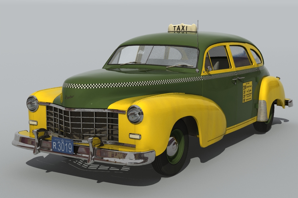
This may be counter intuitive to all those who model showroom pristine cars but I prefer my props to have some mileage on them, especially a taxi cab. There is a dent in each door (the passenger one is somewhat lost in the reflection of the lower hinge) and two in the rear fender. All four use the same normal decal with identical scaling and amplitude. I'm still testing to see whether I get convincing results by scaling just the decal or I have to make small, medium, large and asymmetric dent models.
-
Nothing earth shattering; just a different way to layout patches based on the idea of retopolgy; i.e. using an existing model as a template for a new mesh. The first image shows the original model - the red hood of a 1955 Chevy truck - modeled by Stian and generously lent to me. As you can see he formed the surface in the typical fashion by drawing splines along the major contour lines. But as usual when you have a cylindrical/spherical detail in a rectangular surface you can't avoid generating 3 and/or 5 point patches; which, as you can see in the second image, sometimes are not realistically smooth no matter how much you tweak the bias handles. Believe me I tried. After trying a number of alternate, unsuccessful variations to minimize the 3 and 5 pointers, I realized could likely get the smoothness I wanted if I used only four sided patches. So I made a green copy of the hood in the same location in modeling space as the red original. Next, as shown in the third image, I just did a simple re-arranging and extension of the existing splines to form only four pointers. It was easy to move the new green cp's to lay in the red surface (fourth image). After a little bias tweaking I got the more than acceptable smoothness seen in the fifth image. Granted patch count is a bit higher but it's a small price to pay. Your mileage may vary depending on the desired shape but making a sacrificial template model might be the answer to a particularly vexing surface.
-
4-6-4 Steam Locomotive & Tender
R Reynolds replied to R Reynolds's topic in Work In Progress / Sweatbox
Thanks Brian. It's good to hear from you; a reminder of times when Hash was a going concern. Hey, I learned from the best...you. I regularly open up Eggprops' Metals One and Metals Two to look for pointers. It's been in the budget for some time but I'm waiting to see if AMD's new "Bulldozer" meets expectations. I've always bought AMDs and would only go Intel if Bulldozer's performance is truly underwhelming. So would I, Stian, but I'm still using v13. I have the FedEx notice that my v16 DVD is in town. Unfortunately my optical drive only reads CDs so no v16 until I upgrade all my hardware (see above). I will definitely keep it in mind though. Thanks. -
4-6-4 Steam Locomotive & Tender
R Reynolds replied to R Reynolds's topic in Work In Progress / Sweatbox
Has been for over a year. First I modeled only the moving parts and even before generating rotoscopes for the rest I added bones (see image) and completed the one revolution "walk" cycle action which you can see in post #4 of this thread from March of last year. (No point in finishing a locomotive that can't do the "locomotion".) The stationary parts are a separate model that is added as an Action Object because finding patches and aligning normals of the 47000+ patches of the moving parts model on a 10 year old PC can really test your patience.
-
4-6-4 Steam Locomotive & Tender
R Reynolds replied to R Reynolds's topic in Work In Progress / Sweatbox
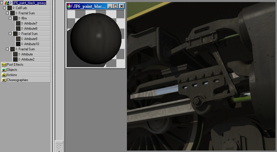
Thanks to everyone for all the kind words. It's not so much a question of technology, just a texture choice. As shown in the attached image, there are a few subtle grease runs on some of the components. If I cranked up the specular size and reflectivity of these attributes in JF6_paint_black_greasy.mat and increased their amplitude I could probably get closer to the look your suggesting. I was trying for the appearance of something that at one time had a nice layer of lubricant but that was hundreds of miles(kilometers) ago, so now fine dirt has caked into the oil leaving only a few darker wet spots. At the risk of sounding like some motivational speaker, you've just got to want it badly enough.
-
4-6-4 Steam Locomotive & Tender
R Reynolds replied to R Reynolds's topic in Work In Progress / Sweatbox
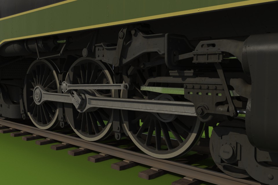
Although there's always one more detail to add or another texture tweak; I'm going to call the locomotive and tender finished. And they've only taken 28 months! More renders here. Time to move on to the next addition to my train set.
-
3rd party material combiners
R Reynolds replied to R Reynolds's topic in Work In Progress / Sweatbox
I was quite attached to a few of the combiners from EnhanceA:M; e.g. A:M_Foliage, A:M_Bricks, A:M_Dirt. But the originating programmer said in an e-mail that it was "very unlikely" that he would do a 64 bit re-build. I agree. Lately I've had some success with rendering these textures on a simple planar model and applying them as decals on flattened models. So I suppose that will have to be my strategy to use them in 64bit A:M from here on. -
I can probably guess the answer but I have to ask; will SimbiontAM, atx & trb files that work in A:M v13, also work in A:M v16 64 bit?
-
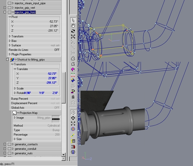
Not really necessary. The cylinder can be any where and any orientation as shown in the attached image. The trick is to apply the Projection material (fitting_grips.mat) to a group (injector_grip_horz) and locally translate the material's pivot to be identical to that of the group (in this case -52.73, 27.05, -291.12). Then you can locally rotate the material to align it with the group (in this case X = 90 deg.).
-
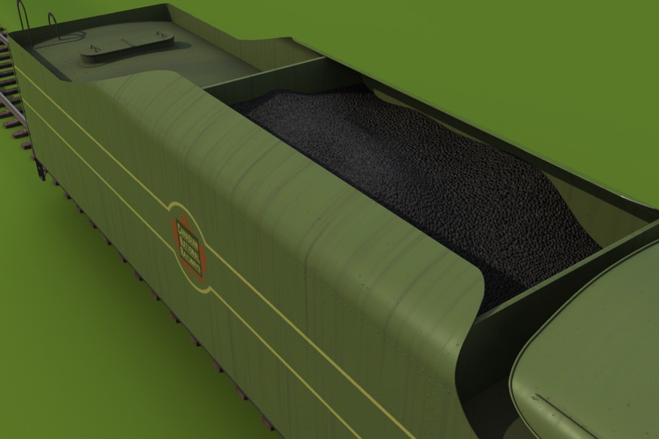
4-6-4 Steam Locomotive & Tender
R Reynolds replied to R Reynolds's topic in Work In Progress / Sweatbox
The tender is more or less finished.