R Reynolds
-
Posts
176 -
Joined
-
Last visited
-
Days Won
47
Content Type
Profiles
Forums
Events
Everything posted by R Reynolds
-
I agree with Michael that I could use a few more views from different angles to get a handle on the shapes you are trying to model. But my feeling is that you're getting caught up in keeping a low patch count and are asking for way, WAY too much deformation of the patches; especially the five pointers (which can be challenging at the best of times). I use bias tweaks for just that, minor shape adjustments; they're not sledge hammers. I think you're going to have to rethink the splinage in the areas I've circled in blue. Draw at least another spline ring around your opening (you may need more than that depending upon your personal tolerance to creasing) and reduce the area of your patches through the convoluted surfaces. Having said that I don't know the construction of the B-36 at all but I wouldn't be surprised if this fuselage dimple is something that is a separate assembly riveted to an otherwise cylindrical fuselage. If that's the case, by building it like the real prototype you could avoid the whole problem and achieve more realism in the bargain.

-
8 oz. glass Coke bottle and cap
R Reynolds replied to R Reynolds's topic in Work In Progress / Sweatbox
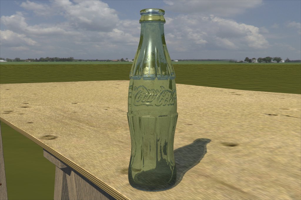
No need for apologies. If I didn't want suggestions, I wouldn't have posted. The bottle group has two materials; the first for the optical properties and the second (shown below at 100%) is applied as a bump material to add texture. It only looks cloudy from this camera angle. As you can see in the entire sky decal below, it's a partly cloudy day and the sun is unobscured. It's always a mild and sunny day in my CG world.
-
8 oz. glass Coke bottle and cap
R Reynolds replied to R Reynolds's topic in Work In Progress / Sweatbox
Original image at thread start has been updated with the bottle cap revised to reflect the various suggestions. Thanks for the input. -
8 oz. glass Coke bottle and cap
R Reynolds replied to R Reynolds's topic in Work In Progress / Sweatbox
The back story is the drinker bought the bottle out of the vending machine just before leaving for the work site and stored it in his tool box. So the top probably didn't have that much time to get blemished but I will probably tilt it's colour closer to a cream. The attached image was my prototype.
-
8 oz. glass Coke bottle and cap
R Reynolds replied to R Reynolds's topic in Work In Progress / Sweatbox
After some tweaking; how 'bout this?
-
8 oz. glass Coke bottle and cap
R Reynolds replied to R Reynolds's topic in Work In Progress / Sweatbox
Thanks David. Not really. Those old scrolling video/arcade games didn't float my boat. Then Castle Wolfenstein was released! Five passes with 52 skylights with shadows. Probably a waste of clock cycles since the bottle's shadow is not that complex but that's my "showcase" lighting setup. More like this?
-
8 oz. glass Coke bottle and cap
R Reynolds replied to R Reynolds's topic in Work In Progress / Sweatbox
I wondered if someone was going to pick up on that. Since it's unlikely this prop will ever occupy this much screen space, I increased my personal tolerance to dimensional accuracy and cheated by reducing the crimp count from the standard 21 to 20 to ease the copy/paste/rotate process. Certainly that would help with the shadows but at this time I'm not ready for the render hit. As it was, this one took 23 hrs. No doubt about it, transparency is expensive. I actually figured out how to model bubbles that rendered correctly but I didn't use them since that's the way this prop (and for that matter 99% of my props) will eventually be used. That's not a bad idea Vern! Do you go when it's busy so the staff is so over-worked that they don't notice you or early in the morning when the staff isn't awake? Absolutely. I've also used a rotary dial phone; a slide rule; recorded music (in analog!) on reels of tape that had to be manually threaded and have actually had to get out of my chair and cross the room to change the television channels. Oh gawd, it was sheer torture. -
8 oz. glass Coke bottle and cap
R Reynolds replied to R Reynolds's topic in Work In Progress / Sweatbox
Yeah it bugs me too. It's caused by the relatively lo-res 1380 X 638 decal that makes up most of the plywood texture. I made the original decal about 13 years ago using my then state-of-the-art, 640 x 480, digital camera. The contractor building the neighbour's house left a plywood sheet in a convenient location so I grabbed three images and spliced them together. I tried to blend in some finer detail using a procedural material but the knots are the most obviously blurry details. Still I sort of prefer it to the perfect, blemish free wood surfaces you get with typical procedurals. (I'd pay real money for a wood material with controllable knots). I hope some day to use my newer 21st century digital camera to make a higher res decal; assuming someone leaves out another 4X8 sheet. Gee, I worked long and hard on that bent pose. Perhaps you're used to twist off bottles caps. There was a time during the last century when you couldn't remove a bottle cap without severly distorting it's shape while using a metal tool called a bottle opener. Since everything in my CG world lives in an early 1950's time frame I felt the bent cap was appropriate. -
Everything except for the bubbles.
-
Odd render anomaly with multi-pass skylights
R Reynolds replied to R Reynolds's topic in Work In Progress / Sweatbox
Yikes! I was kind of hoping no one would ask because looking at my old rig now, knowing what I know about how it works in multi-pass, it just looks ludicrous. I sort of stretched the the truth earlier when I said some of the bulbs' volumes went below the horizon. However, confession is good for the soul, so here's a comparison of my former really-big-skylight setup (on the left) and my new, more proportional one (on the right), arrayed around my standard 3 mile diameter sky dome. The increase in the illumination of a scene using the new setup is quite noticeable. Behold 19 mi. diameter bulbs! Let the derisive laughter begin.
-
Odd render anomaly with multi-pass skylights
R Reynolds replied to R Reynolds's topic in Work In Progress / Sweatbox
Anomaly corrected. After some testing it turns out that my problem was due to making the skylights very, very large in an over-zealous attempt to soften their resulting shadows. So large in fact that the volume of the bulbs near the horizon actually extended under the models. My testing showed that multi-pass treats a huge bulb as a true area light; randomly sampling rays from anywhere on it's surface. So it was quite possible to trace rays from below the models, hence putting them in shadow and making them darker with each pass. (the first pass was always the brightest because I assume the first sampled ray comes from the bulb's centre point, above the horizon). So it's important that the entire volume of a skylight bulb be above the horizon. -
I've discovered a strange thing when using 5X multi-pass rendering with skylights in v12.0n+. As shown in the attached image I have two spheres in front of a flat shaded skydome. The first sphere has a diffuse colour of 128, 128 128 while the second is 255, 255, 255. The first pair of images shows a comparison of lighting the spheres with a single klieg and rendering an image with and without multi pass. As expected, no noticeable difference. However in the next image set, I turn off the klieg and turn on my 52 bulb skylights (a variation on one of Yves' setups). The first image shows the render with no multi-pass. The next five images are images after turning on 5X multi-pass and doing a screen grab after each pass. The first pass looks fine but with each subsequent pass the spheres' illumination drops and the overall shading becomes more generalized. I'm worried that there is something unusual about my skylight rig. Would someone please confirm this anomaly using a different skylight setup? Thanks.
-
Decal Challenges - Continuation
R Reynolds replied to pixmite's topic in Work In Progress / Sweatbox
Sorry, I'm stumped. I quickly built a similarly shaped "fuselage" and decaled vertical bump stripes on it in the manner you described and they produced the expected results without any of the strange discontinuities you're getting. My only suggestion is to make a test copy of just the fuselage as a new model and strip out all decals and materials. Then starting with a new project and a clean model, apply only the bumps maps and see if you can reproduce the problem.
-
Decal Challenges - Continuation
R Reynolds replied to pixmite's topic in Work In Progress / Sweatbox
Would you please post a shaded wire frame of the same area of the model? I've had similar problems when decals are applied to hooks. For the bump maps that are the wrong polarity on the right side, you flip those bumps by opening up that decal image and setting it's bump percentage to a negative number. Decals tend to follow the curve of splines (which is probably great for applying makeup to a face but for painting racing stripes on car hoods, not so much). The only sure solution I've found is to increase patch resolution (maybe 2 or 3 times) in the region where you want straight and orthogonal decals and then get absolutely obsessive over making sure all splines are as straight and even as possible. In one case I had to draw a pre-distorted decal (using an iterative process) which the decaling alogorithm then took out on application. Ah the joys of building machines with an app optimized to animate characters. -
I'm not convinced that there is anything wrong with the optics your glass, it appears to me to be a refracted image of the sky combined with the reflected image of the table. Try moving the camera up about 7.5 cm, re-centering the glass in the fov and do another render. Then move the camera down about 15 cm, re-aim and re-render. You may find the results instructive.
-
I agree with your analysis Stuart. I assume that turning on caustics (radiosity) would solve this inaccuracy but don't have the patience to find out at this time. And even if the shadows are still wrong we must remember that A:M's demographic priority is people who think character driven animated movies are cool, not those who are turned on by accurate simulations of reality.
-
Thanks David, I'll give it a try once I'm finished with the bottle cap. Well it started as one of Yves' skylight rigs. I originally downloaded it in v8 but it didn't import correctly in v10. So out of frustration with this lack of reuseability I individually positioned each light in the chor. (using Yves' x,y,z coords) at which time I also tweaked it to get more even illumination over roughly a quarter mile of landscape. At the time I felt the shadows from 25 lights still had too much granularity but that was before multi-pass capabilties. I'll probably do some more experimentation at some future date. I didn't turn on the skylight shadows since this was just a WIP. When I render for prime time, they'll be on. The same as for the outer group, i.e. the average value I got when I googled "index refraction soda lime glass" (your standard cheap window glass), 1.5.
-
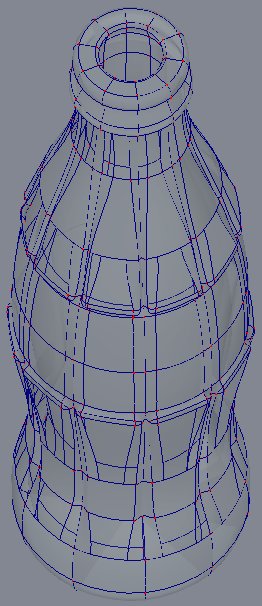
Thanks for the kind words. I have found that the key to texturing hardware is adding small bumps and defects to the surface. Perfection is not only over-rated but it's also unrealistic. It is unibody (see attached image) but the model is divided into two groups of patches with a tweaked material on the internal group. I assume its shadow would be more realistic if I turned on caustics but even I'm not that patient when it comes to render times (see below). I couldn't agree more; that's why I didn't post to Showcase. I have yet to see an image that when used this way doesn't look like a repeating tile. Would you be able to point me in the direction of suitable images? Ultimately my background landscapes will have meadow-like grasses but I didn't want to take the render hit in this case (see below). 10+ hours on an Athlon running at 1.5 GHz; 1024 X 683; 5X multi-pass; no soft reflections; no caustics; the sun is a klieg casting 2 shadows; there are 58 bulb skylights casting no shadows I tried turning on caustics and reduced most of its default values by a factor of 10 but the first pass wasn't done after 5 hrs so I gave up. I'm assuming for my purposes grass and radiosity won't be practical until CPUs all have four embedded processors and A:M code is written to use them all (I'm guessing by 2013 when I turn 60). Although I must admit the chances of a Coke bottle taking centre stage on my CG railroad are pretty slim; thank the gods locomotives are opaque. I pity the person who wants to render Wonder Woman's glass jet.
-
Your basic small, glass, Coke bottle. I found that I could noticeably reduce render times by separating the bottle surface into two groups, external and internal. I applied the same material to both groups but I modified the internal material instance by turning off its reflections. Even with a two reflection bounce limit it still made a difference.
-
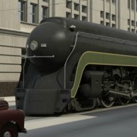
Congratulations, you've discovered the most useful tool for modelling smooth mechanical surfaces in A:M. You seem to have reached the inevitable point in the battle of tweaking vs. time that I call the "SCREW IT...IT'S DONE" point. But I do have a few suggestions to improve what already is an impressive model. There are three obvious regions (illustrated in the attached image) that still require some work, IMHO. 1) The leading edge of the hood just behind the headlamp unit has a bit of a bulge that should respond to bias tweaks. 2) I don't have any confirming reference pictures but the distortion in the seam between the hatch and the rear quarter panel looks wrong to me. 3) The crease at the leading edge of the door handle pocket is similar to an actual sheet metal defect that happens fairly often. (Some stamping plants call them "rabbit-ears" since they tend to occur on both sides of the pocket.) Although they allow a certain amount of such distortion I don't think your creases would pass plant specs. Lastly, you currently have external panels that have no corners; they're simply infinitely thin curved surfaces, floating in space. You may hope that once the underbody and interior are in place, they will disguise this inaccuracy. But I think you may be disappointed by the look of the car in close-up.
-
What sort of device/software combination do they use to convert the marks taped to the car to points in 3D space and how long does the process take? I'd also like to see a wireframe of the imported model. Thanks.
-
Alternately, I might suggest setting the surface properties to the following: diffuse colour = 128, 128, 128 specular colour = 255, 255, 255 specular size = 60% specular intensity = 60% and use the changing shape of the specular highlights (which you can view in real time as you move the surface) to find unwanted creases.
-
I understand you're reluctance to add patches. (It still needs more detailing!) I took a look at you're fuselage and my first thought was that you're hurting yourself by not having continuous splines running aroung the edge of the windows. So I took the worst case (the long thin 5 pointer aft of the third porthole and made some mods and did some more tweaking (see attached image). The edge of each window is defined by four continuous splines with mags of 33 at each corner and the gammas tweaked so the splines defining the external and internal skin are aligned properly. The downside is the window edges are slightly convex. The next step was to isolate only the splines that define the 5 pointers and their immediate neighbours and view them in wireframe in a front view. It was clear that both the cps of the central vertical spline was slightly out of alignment with the fore and aft vertical spline. The adjustments I made (CP lock is perfect for this) don't produce an ideally smooth surface, then again neither is the skin of most aircraft, but you may find it good enough. BTW, I tried these last tweaks without making the window splines continuous and was unable to get the same level of smoothness.
-
The prototype for this model (including the texturing) is hanging in my garage. shovel renders I toyed with the idea of simply using a photo of the blade to decal the texture but I've been forcing myself to use more complex materials because I'd like to think that dealing with the pain of tweaking procedurals, builds character. I did use colour samples from my reference photos in the materials.
-
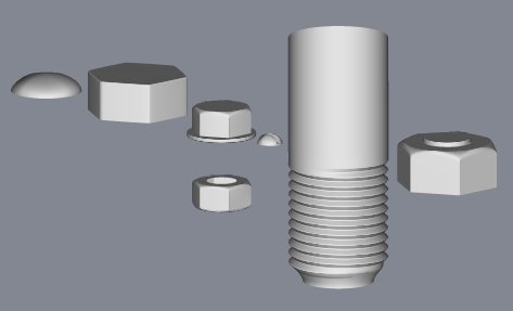
"I would be most grateful if you would make it available." This thread has spurred me to update one of my web pages. rivet tute At the bottom of the above page is the following image which links to a zip file containing the models of these generic connectors. You're welcome to them.