R Reynolds
-
Posts
176 -
Joined
-
Last visited
-
Days Won
47
Content Type
Profiles
Forums
Events
Everything posted by R Reynolds
-
Sorry, that's a questions of personal taste. One person's sweet ride is another person's jalopy. For instance, possibly you (and maybe a fair number of A:M users) think the car on the left, a 2006 Bugatti, is cool. While I think the 1937 Bugatti on the right is far and away cooler. As you can see, I'm not that enchanted with present auto design trends. At any rate, you'll have to choose a model that appeals enough to you that you won't lose interest during the modeling process.

-
Pretty much everything I have to say on automotive modeling in A:M is contained here; automotive modeling tutorial
-
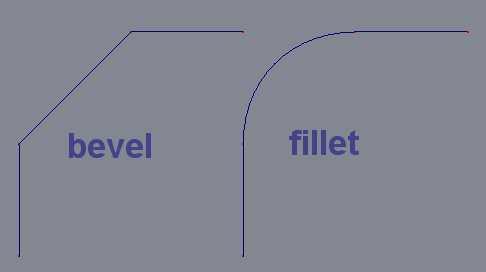
First I'd suggest you get the terminology correct. A corner consisting of flat planes meeting at angles less than 90 deg. are called beveled corners. A filleted corner is the name for a round corner. It's a common trivial error but you might as well start off right. It sounds to me like your being annoyed by the way A:M naturally adds cps. By its very nature, when inserting cps A:M automatically adjusts surrounding bias values using an algorithm that's optimized to ease character animation not mechanical modeling. So your best solution is to build in the fillets from the very first spline not add them into existing surfaces. You may want to check out these web pages for suggestions on modeling rounded corners: Yves suggestions My suggestions Before you hit the add cp button, hold down the shift key. But this only adds a new cp equidistant from the neighbouring cps on either side. To make a fillet it's usually essential to have two closely spaced cps to define either end of the round shape. If you shift/add a cp in the middle of a spline and drag it to one end to form the corner, all those bias values (which were automatically calculated by the shift/add function) will once again be incorrect for realistically smooth automobile sheet metal. I doubt there's a best way but I'd prefer a web page because they are low bandwidth and a student can randomly jump to different steps at their convenience (something that's not so easy with a flash movie).
-
Of course the look of your balloon is a choice that's yours to make but I would prefer to see the ropes cutting into the envelope less severely and have the envelope look smoother and tighter (see image). As it stands right now it appears to me that it's a tightly wrapped pillow. If you want the balloon to have texture you can always add a bump map that won't betray it's spline construction.
-
Have you tried enclosing your model with a bulb type light source larger than the glass envelope? I think you'll have to turn multipass on so that the exterior of the source is sampled and not just the origin (just spit-balling, haven't tried it).
-
Railroad Station Waiting Room
R Reynolds replied to R Reynolds's topic in Work In Progress / Sweatbox
Personal. (Oh, if I could only get someone to pay me for modeling such things.) Someday, after I finish the other 3/4 of the entire station complex; commercial arcade, waiting room, concourse and train shed, I'd love to do a SteadyCam, tracking shot from street entrance to boarding the train. As tempting as it is to build the entire thing as a one model, there's so much repeated detail that it didn't seem practical. As well I have a philosophical problem with assembling something in the chor; it just doesn't seem "right". So I'm building this room using Action Objects in an action files; 59 objects and counting. -
Railroad Station Waiting Room
R Reynolds replied to R Reynolds's topic in Work In Progress / Sweatbox
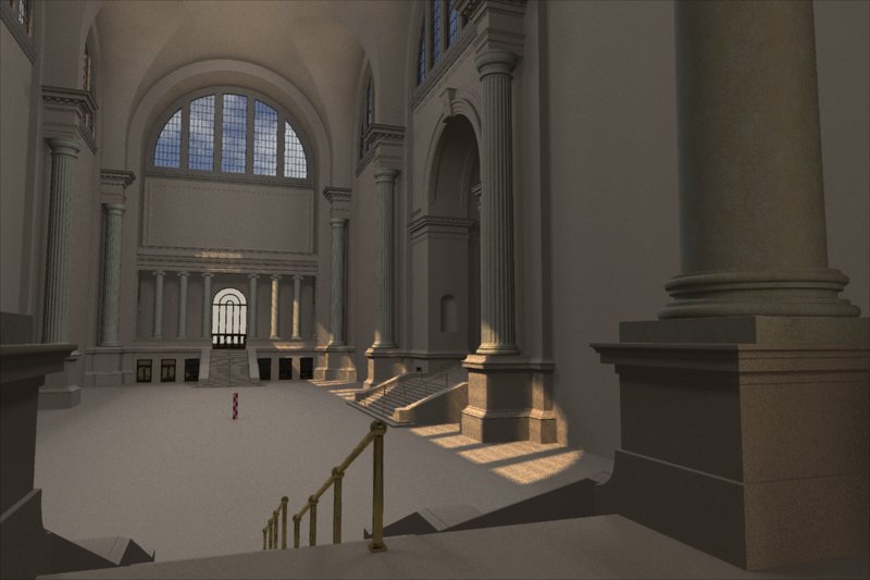
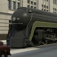
It's a close reproduction of the now demolished Pennsylvania Railroad station in New York. It was built during the same era as the stations you described; a time when the railroads were the engine of the economy and their CEO's were some of the richest men on the continent. They built these huge stations as shrines to their "obviously superior" business skills. Not yet. The perimeter wall divides into eight sections, three of which are almost finished (see attachment). Part of the reason for the close-up was to give me good look at the iconic column tops. They were a major pain. Neither, I tend to never use a new feature for a version or two while the programmer's work the kink's out. I guess you'd call my lighting, old-school overkill. It's all raytraced using an array of 90 kliegs to simulate skylight and bounce light from the surrounding buildings and streets. I tried to use less but the wide vertical columns in the lunette windows kept casting shadows within the room. The sunlight adds another two kliegs and then there's four sun lights to fake bounce light from the floor. All in due time. For now all I can offer is my checkered, 6 ft. reference cylinder.
-
The sun probably needs more rays cast to further diffuse the shadows from window muntons and I think there should more light coming from the street through the upper entrance but it's getting there.
-
Nice headlights! I've been watching your impressive progress with the Chevelle and I think it deserves that extra bit of tweaking to get the external sheet metal meeting plant specs. I've circled, in green, the areas where, IMO, two adjoining parts don't match in shape. The roof is circled in red because it appears to me, especially in head on views, that the roof is slightly concave. I'd suggest you grab parts of the central spline, move it up by about 1/8"- 1/4" and tweak the bias of the cross splines accordingly.
-
Golden Gate Bridge High Detail model
R Reynolds replied to MMZ_TimeLord's topic in Work In Progress / Sweatbox
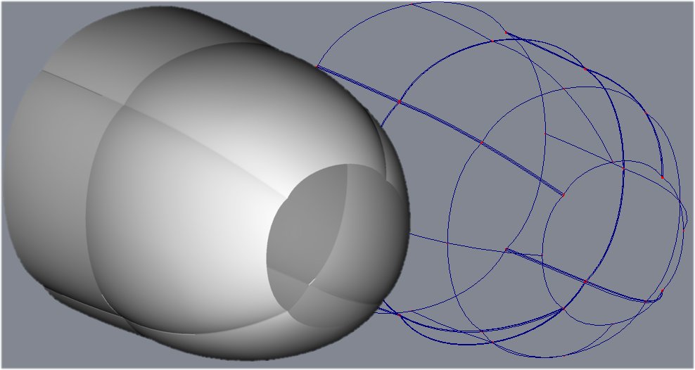
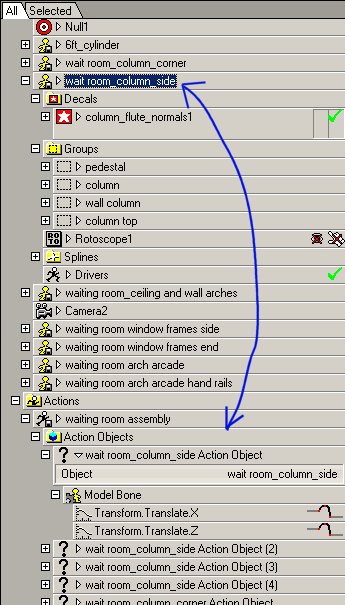
I guess action objects are treated differently than when you are manipulating the base model. As you can see in the attached image, the model I brought into the action has both groups with materials and decals but none of that is exposed as a fully expanded instance of an action object. Mike has a work around but it means assembling the model in a chor which doesn't seem as elegant to me. Can you drop poses on action objects?
-
Golden Gate Bridge High Detail model
R Reynolds replied to MMZ_TimeLord's topic in Work In Progress / Sweatbox
No. Neither in the chor nor the action. Unless I'm missing something, there's no access to tweaking anything within the imported objects, just their location and orientation. -
Golden Gate Bridge High Detail model
R Reynolds replied to MMZ_TimeLord's topic in Work In Progress / Sweatbox
Excellent start. May I suggest you experiment using Action Objects. I am currently using them to build a large building with a lot of identical but repeating detail and am so far quite happy with the result. It's also how you multiply one light source into a skylight rig. In the case of the the bridge you start with a new action using some base model, say the finished tower. Now you can import a new object into the action; i.e. a copy of the tower but positioned to be the north tower. Next import and position multiple copies of the roadbed to build the bridge. The beauty of this process is that you can build a highly detailed structure and still keep the patch count reasonable. (And with the new displacement feature in v13, you can add 3D rivet heads as repeating decals). You'll run that same play again for the lights; make a new light source then import and position copies inside the action. Once you're in a choreography, you import and position the base model, apply the "construction" action and your bridge is built. So far, the only downside I can see to building structures this way is you'll have to keep the texturing fairly subtle on each model sub-unit because that texturing will repeat as well. -
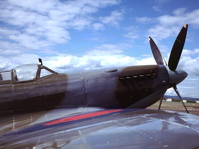
It's an excellent start but I think you're unnecessarily complicating the model by making the frame of the canopy an integral part of the fuselage. Based on this reference image I found on the web, the windscreen frame is a separate, riveted assembly.
-
Bumps and normal decals are just rendering tricks that (as shown in the attachment) break down at oblique viewing angles. The block really only has a flat face. But considering that the keystone is at the top of an 85 ft. arch it shouldn't be too hard to pick camera angles that maintain the illusion. However as oakchas points out, with the new displacement implementation in v13, the stone may still have a flat face but the figure will actually protrude from it; pretty dang cool. To use it, all I have to do is replace my normal map attribute with a gradient map to get a correctly shaded decal.
-
Yes, the new displacement implementation is the main reason I'm saving for v13. But don't get too carried away about being able to use any photo. As in bump maps, the greyscaling in your 2d image must be proportional to Z coords. Your average photo isn't even close to this. To get accurate results you'll still need a render of a 3D model with a black to white, Z axis gradient material.
-
This turned out way better than I had any right to expect. I'm working on a large, beaux arts style, arch that needs a keystone with a classical human figure carved in it. Looking for inspiration on the Web, I came across a free 3D model of a nicely proportioned and posed female figure, unfortunately in 3DS format. After waiting almost 8 hrs. for it to import into A:M (47,000 patches, 8.3 Mb model) I knew that I couldn't add any new splines to the model since finding patches and aligning normals took a LONG time. All I could do was apply aaver's normal map material and render out a rotoscope. Using the rotoscope as a guide, I built surrounding splinage to smoothly blend the figure into a flat surface. Once again I applied the normal map material to the figure's "frame" and screen rendered it along with the rotoscope. I little re-touching in PSPro to hide the seams and I have nice bas-relief for my arch's keystone.
-
In my opinion you could solve a lot of your corner problems (both those on the bottom of his feet and around his mouth) by defining the corner in each spline with two cp's instead of one. By having a cp at the leading and trailing edge of a rounded corner you have much more control of the shapes on either side of the corner. You might want to read a couple of tutorials. I refer to making rounded corners as filleting; http://www3.sympatico.ca/rodger.reynolds/f...fillet_tute.htm While Yves calls it beveling; http://www.ypoart.com/tutorials/bevels-intro.htm The seam along his eye hood looks like you have the bias peaked. Try selecting the smooth default.
-
That's a cool instrument panel. I'm curious to see it's wireframe to get an idea of the splinage to decal ratio.
-
Fabulous!
-
It's at times like these that I need to go back to basic principles and do a quick and simple experiment to learn what's happening. I suggest the following; - start a fresh project with a new model and a copy of your decal - the new model is a simple cylinder with its long axis vertical lying along the Y axis - due to the model's location and orientation, cylindrically mapping the decal on it should be straightforward - now using the numeric inputs, move the model a known amount in X or Z to see what happens to the decal - using numeric inputs, rotate the model around the X and Z axis to see what happens to the decal - now move and rotate the decal the same increments and see if you can re-align the decal Once you've taught yourself the proper technique, write a quick tutorial text document while it's fresh in your mind and store it in your AM_mini_tutes folder
-
After you've applied the material to the desired group you can translate and rotate that particular instance of the material. Pick the group, note its pivot coordinates and then translate that group's material to the same coords and rotate it as required.
-
"Now you can set it as either a bump or displacement map." With the new displacement, I question the need for bump or normal maps. Would someone please do a comparison to gage the render hit?
-
Excellent work. Are you using bump maps for the front tire treads?
-
My apologies as I was unaware of your task. Motivating potential TWO contributors with a free copy of A:M is perfectly understandable.
-
Perhaps I'm being overly sensitive or don't sufficiently understand what this restriction implies but wouldn't this be the first step down a path that would turn those happy few you get satisfaction from using A:M for projects other than character animation into second class citizens of the community?