R Reynolds
-
Posts
176 -
Joined
-
Last visited
-
Days Won
47
Content Type
Profiles
Forums
Events
Everything posted by R Reynolds
-
Displacement map shading behavior
R Reynolds replied to robcat2075's topic in Work In Progress / Sweatbox
Careful how you mirror normal maps, they are very orientation specific. I modeled two hemispheres, convex on the left, concave on the right, and applied the normal material to both. Notice that to make the left map look like the right, you'd have to mirror it in both X and Y. Flipping a normal map in a paint program, in only one axis, gives unexpected results.
-
4-6-4 Steam Locomotive & Tender
R Reynolds replied to R Reynolds's topic in Work In Progress / Sweatbox
I have two pieces of instrumental music in mind that I think would make good soundtracks for short videos involving my railroad. Kinda like Fantasia where the music inspires the action. I model everything "full" scale except for the sky dome (a quarter mile diameter hemisphere) within which my railroad exists. As you point out, it does matter because there are accuracy limits to the floating point operations at the heart of A:M. There really are objects that are too big or too small to model in full scale. So if you wanted to do a "cosmic zoom" shot from a planet to a paramecium you're going to have to cheat the scale. (The reason for my quarter mile sky). Although I wonder whether the move to a 64 bit environment expands our modeling limits. Don't even mention it. Distractions make richer discussions. -
4-6-4 Steam Locomotive & Tender
R Reynolds replied to R Reynolds's topic in Work In Progress / Sweatbox
Ya'got me there but I'd be more impressed by your husband's nitpicking if he'd noticed that this movie prop locomotive never existed; combining the layout and running gear from the first prototype shown, the streamlining and paint cues from the second and the colour palette from the third. The movie's producer/director told the production designer "I don't care if it's an authentic reproduction, it just has to look cool and believable, to me".
-
4-6-4 Steam Locomotive & Tender
R Reynolds replied to R Reynolds's topic in Work In Progress / Sweatbox
I'm in the midst of adding colours such that it looks like it was washed some time ago; not too dirty but not too clean as well. Still trying to find the right balance between material dirt and decal dirt.
-
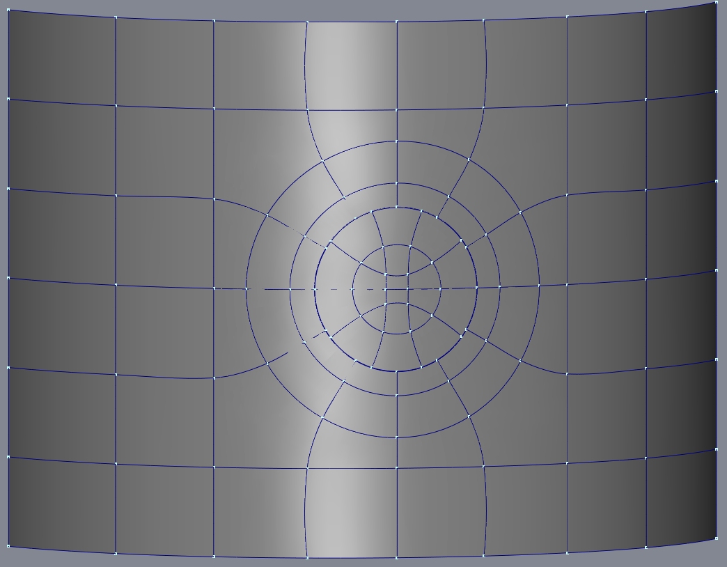
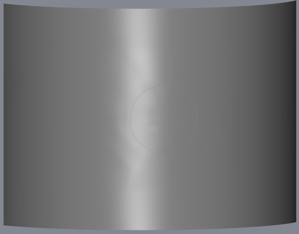
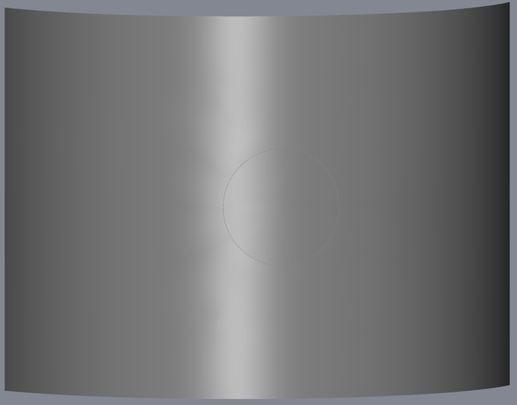
This is my best modeling suggestion. (You might be able to get away without the second spline ring from the round cutout.) The minor variations in the specular reflection shows it's not absolutely boolean perfect but it's dang close. The second image is unfiltered splinage while the third has normals averaged using "porcelain". I didn't split the cylinder but I think that should be straightforward using this layout. OH! You wanted simple! Sorry, you can't always expect "simple" if you want a certain level of quality.
-
4-6-4 Steam Locomotive & Tender
R Reynolds replied to R Reynolds's topic in Work In Progress / Sweatbox
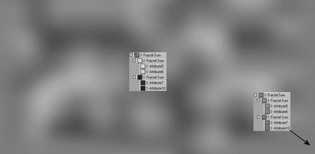
All textures comes from images generated within A:M, normal decals generated using MakeNormalMap (documented here) and massaged in Paintshop Pro. First flatten the section of interest in an action, decide where you want sheet metal joints (e.g. every 60 inches (1.5 m)) and put markers at those locations. In a separate model (see first attached image) build a flat patch 60 inch long with a "joint" (actually a 1/8 in. (3 mm) trough whose normals will render well) at one end. Copy and paste models of rivet heads at appropriate intervals along the joint and do a screen render. Import the screen render to the paint program and replace the rendered rivet heads with the Phillips head screws normal maps from here. Apply these screwed joint normal decals at the marked intervals on the flattened model. Build another flat test surface with the same dimensions without any joint and apply a material with a combination of Fractal Sum combiners. The primary or outer Fractal Sum is scaled to represent the larger waves across the metal sheet, grey values above 127 are hills and below 127 are valleys. The hills and valleys are also built from their own secondary or inner Fractal Sums with much smaller scales to represent the paint texture commonly known as "orange peel". These inner combiners use the same grey value difference of 8 levels for the hills and valleys so the orange peel is the same over the entire surface. For instance an almost flat painted panel texture uses four grey values close to 127; 140 & 132 for the hills and 124 & 116 for the valleys while a wavy panel uses 216 & 208 for the hills and 48 & 40 for the valleys. (Finding theses values by trial and error with full renders as feedback can consume a lot of time). Screen render and grab the section twice, once with material grey values that represent an almost flat panel and again with wavy panel grey values. In your paint program combine the two images with very diffuse transitions so the central section is wavy while the screwed edges are almost flat (see second attached image). For each metal sheet on the model, move the material on the test surface by much more than 60 in., re-render and massage. Finally apply each image as a bump decal so it's edges align with your normal decal joint edges. Since the bumps on each decal are mismatched at the joint you'll reinforce the illusion that they are individual panels. Clearly this not as easy as using the roughness settings but it gives you WAY more control over the look and location of the surface finish.
-
4-6-4 Steam Locomotive & Tender
R Reynolds replied to R Reynolds's topic in Work In Progress / Sweatbox
Almost finished decaling the sheet metal details to the locomotive. Trying to find a realistic level of waviness took a lot of trial and error with the decal contrast. The only good way to see it is to have the surface reflect the surroundings which slowed the turnaround time on test renders.
-
4-6-4 Steam Locomotive & Tender
R Reynolds replied to R Reynolds's topic in Work In Progress / Sweatbox
The streamlined sheet metal jacket on the locomotive is attached with a lot of sheet metal screws. I didn't want the patch overhead of modeled screw heads but normal mapped hex heads just weren't convincing. The best compromise was button head Phillips. They'll work in most shots as long as the camera doesn't linger too long. The screws heads shown in the image are 32 x 32 pixels which means for 3/4" (19mm) heads they have a resolution of 0.02" (0.6mm), more than adequate. For the interested few I'll upload the four hi-res normal decals (648x648) to the Images section of Shared Resources.
-
4-6-4 Steam Locomotive & Tender
R Reynolds replied to R Reynolds's topic in Work In Progress / Sweatbox
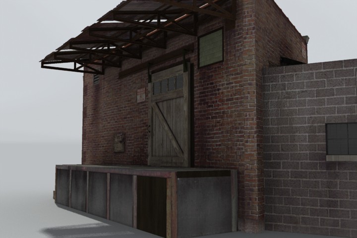
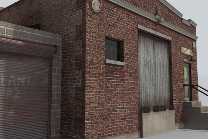
I use bump maps when I'm trying to simulate small dimensional surface variations like waviness or paint textures. Normal maps are more useful in simulating details that have serious surface geometry. For a rail side building, I wanted to use a normal decal for an architectural rosette detail. I built the detail from splines (shown in the center of the image) and used it to generate a bump and normal map which I applied to either side of the original model. Although neither decal can match the original patches, the normal decal comes closer.
-
4-6-4 Steam Locomotive & Tender
R Reynolds replied to R Reynolds's topic in Work In Progress / Sweatbox
Since it's just a big flat sided box, the tender's an ideal test site for textures and materials. The surface shown is mostly just a dozen totally flat patches. Each riveted panel is built from one normal decal for the rivet heads and one bump decal containing the sheet metal waves, overall paint texture and the vertical seams. The bump textures all started as Fractal Sum materials, screen rendered and combined in PSPro.
-
4-6-4 Steam Locomotive & Tender
R Reynolds replied to R Reynolds's topic in Work In Progress / Sweatbox
Thanks for all the kind words. That only happens with those new fangled electric locomotives like DJBreit's GG1. I must confess, seeing it crash through a wall and then through the floor would be a pretty cool sequence!
-
The modeling is 99% done but I'm going to see how much detail I can add with normal and bump decals. I'm really impressed with how well normal decal rivet heads hold up under fairly close scrutiny, as shown in the shot of the rear of the tender, even when they're next to the modeled rivet heads attaching the handrails and ladder. By modeling the decaled heads with a low profile their lack of self shadowing isn't obvious in sunlight at grazing angles. The only downside is you can't apply a left hand normal decal, mirror it and apply it to the right side since the "polarity" of the mirrored decal is wrong, as shown in the third image. So you have to generate left and right side decals. Still far easier than adding modeled rivets.
-
Beautiful toy, Stian! Since all the valve gear components are simply rotating about end pins I found it more intuitive to set up the bones to use nothing but roll handles, except for the main connecting rod, see attached. The downside was that for rods that were rotating at both ends I couldn't figure out constraints that connected both ends. So I went through the 60 frame one revolution action and aligned the ends manually. I assume that Thomas and his cousins don't have accurate valve gear and it's best to model what they use. Should anyone ever lose their mind and starts investigating "real" locomotive running gear, I can recommend a number of graphical locomotive valve gear simulators that I found invaluable for showing me how the various types function.
-
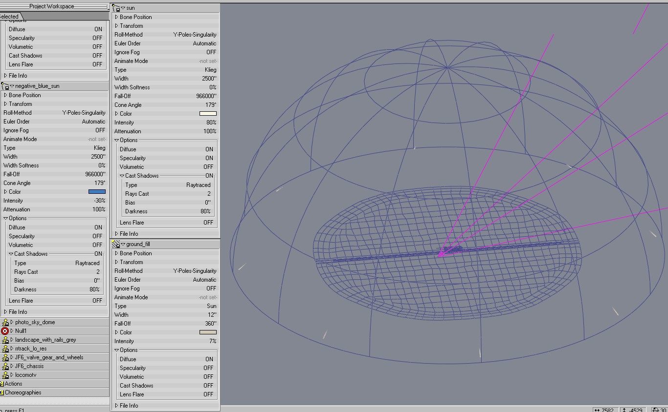
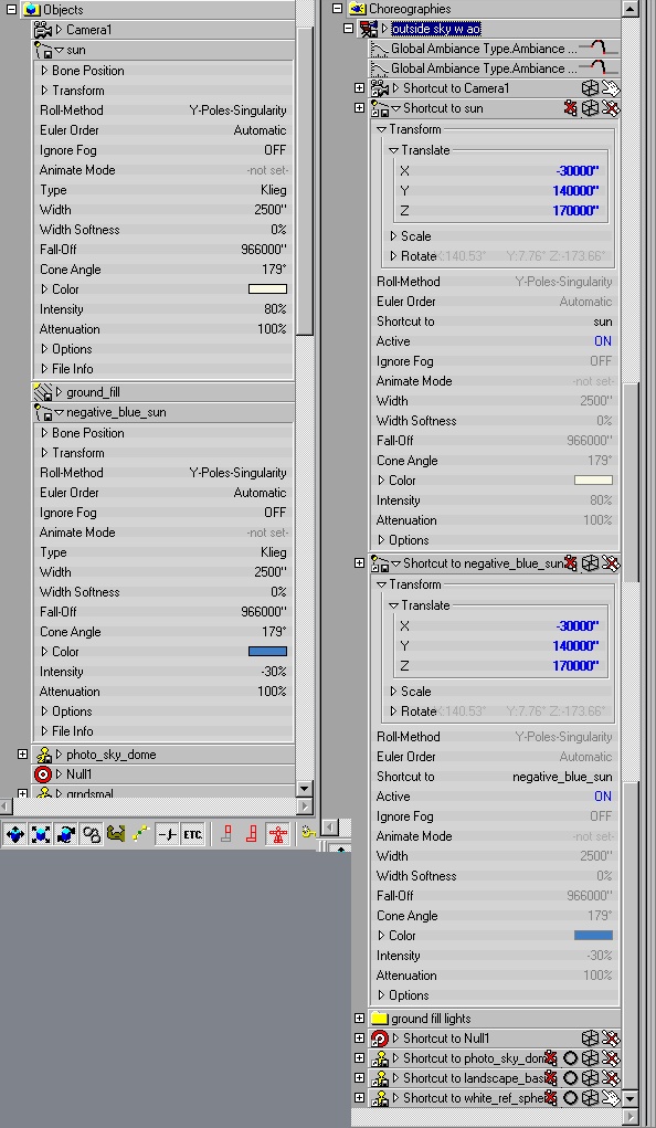
What I was going for with this lighting set-up was an all purpose, convincing sunny day outside environment. With that in mind, any object (that isn't itself a light source) that gets put in this environment and looks wrong needs to have it's materials adjusted not a special light. The way I use a skydome, it's only there to support the decal of the sky. Its ambient intensity is at 100, casts no shadows, receives no rays and as such has no effect on the lighting setup.
-
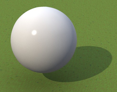
I see all kinds of strangeness in that image. There's something odd about the ties and ballast (stones) underneath the rails. I can see the shadow of the locomotive falling on the rails directly in front of it but nothing below that. The sides of the tunnel are in deep shadow but the ties and ballast inside are not. The chassis of the truck doesn't seem to be shadowed by the flatbed trailer and the cargo of pipes don't seem to cast shadows on the flatbed. The interior of the loco should be totally shaded and yet it's glowing red. My guess is there's some material effects going on. Are the ambient intensities of all your materials set to 0? I'd suggest deleting all materials and use the same shade of grey on everything just to give you a neutral starting point. I've attached a render of what a 2 ft. diameter cue ball looks like in my lighting setup. Its white RGB values of 212, 212, 212 took some experimentation to find the right balance with respect to it's specular highlight. I suspect your going to have to adjust all your materials to make them work in this lighting setup. My solution was to put a Null at the centre of the scene and constrain both suns to aim at it. Then I move both suns by changing their X,Y and Z numerical values. I suppose there's some way to lock the negative blue sun to the white sun so you only have to change one set of values but I've never looked into it.
-
The softness of a shadow is only dependent on the light source size, the distance from the source to the shadow casting object (shorter distance = softer transition) and the distance from the object to the surface on which it shadow forms (longer distance = softer transition). More rays just reduces the shadows' granularity, as you say making it smoother, but increases render times. So if you wanted to show a character walking through the shadow of the peak of the central spire of Stian's Nidaros Cathedral and you wanted convincing ray traced shadows, prepare for longer waits.
-
"The Eyeball and Fudge" Great name for a pub.
-
That's correct. My first objective was to put the sun as far away "as possible" from the characters such that in really high, long shots it's not obvious that the shadows are not all as parallel as they are here on Earth. Three miles seemed reasonable. The second objective was to pick a sun diameter that produced convincing soft shadows. To calibrate this I took my camera, a ruler, a protractor and a sheet of white cardboard and found a flag pole with no flag flying on a sunny day. Using the angle of the shadow and it's length I estimated the flagpole's height then took a picture of the shadow it's top cast on the cardboard with the ruler lying in the shadow's transition from full sun to full shade. Armed with this known shadow I modeled the flagpole and a ruler in A:M and rendered images of the shadow on the ruler with different sun diameters. 2500 inches produced a similar looking transition. It's all crude, back-of-the-envelope calculations and personal judgment, but then again I'm the final customer.
-
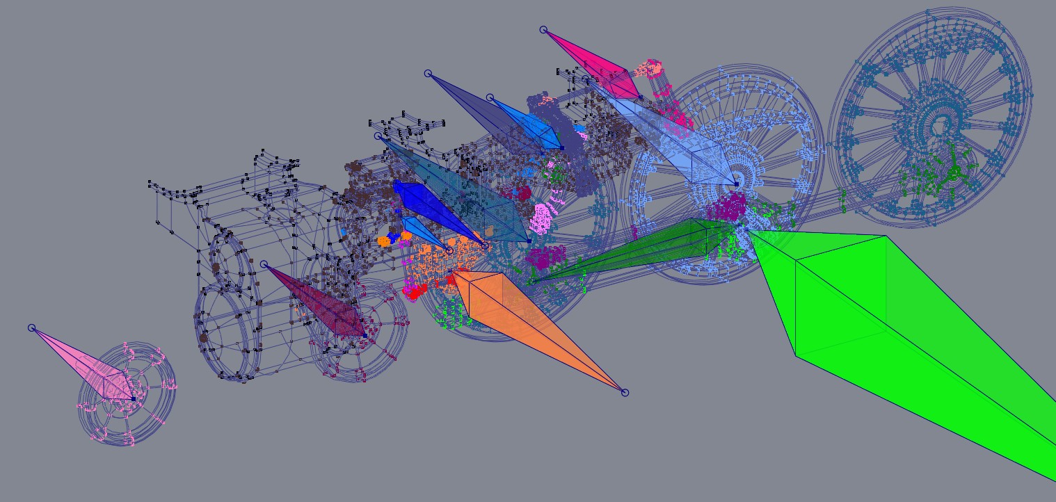
I always use at least 2 rays per sun. Raytracing ensures (referring to the earlier render I attached of an old building) the shadows from the handrail falling on the nearby wall are sharper than those cast by the building's corner on the more distant garage wall. The last time I tried them, suns don't produce controllable soft shadows with ray tracing. I only use sun type lights (eight of them with no shadows) arrayed around my sky dome's perimeter to simulate bounce light from the ground to help fill in the shadows under overhanging roofs. See attached images. I should also set the record straight that Yves Poissant is the originator of the negative blue sun shadow technique and kindly shared.
-
I get soft shadows that I find convincing with klieg "sun's" whose diameters are about 200 ft. and 3.5 miles away from the characters.
-
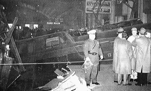
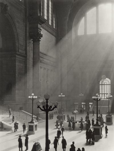
Thanks. Nope, the closest I've come would be a trip to Newport, Rhode Island. But if you do any research into the glory days of railroading you can't help but run into pictures like the one attached of the stations' waiting room and who wouldn't want to experience such an over-the-top room? But since I can't ever visit such a cool building, the least I can do is build one to use in my own films. Well, not at the moment (you see there's this locomotive ) but it's still in the WIP stack. In the late summer of '09 I was doing test renders of the station's below street level taxi stand when I felt the need for a 50's style Checker cab to get the lighting right. By the winter I was getting somewhat frustrated trying to flatten the cab's back roof and rear quarter panels to apply the belt line checkerboard pattern decal when I got the final locomotive reference material for Christmas. Since then I've decided to try to concentrate on the star of my films before I get back to the supporting cast and sets. But fear not, my Penn Station set will be finished (eventually).
-
Apparently not! I took just the offending components and some nearby parts to create the same shadows and positioned them identically in the same project with the other models turned off. They render perfectly, no strange granularity anywhere. This suggests there's some very specific interaction within the full locomotive. Since the loco is one of the few models I'm unwilling to share I guess I'll plead temporary insanity, thank everyone for their suggestions and tell you to go back about your business. Nothing to see here! You're absolutely correct, a 4-6-4 hybrid that never existed in reality; the running gear is modeled after a Milwaukee F6 while the streamlining and cab are similar to the N&W Class J. Well, you can't run a railroad until you've built a railroad. And like any train trip, half the fun is getting to the destination. At least I have the action for one revolution of the wheels.
-
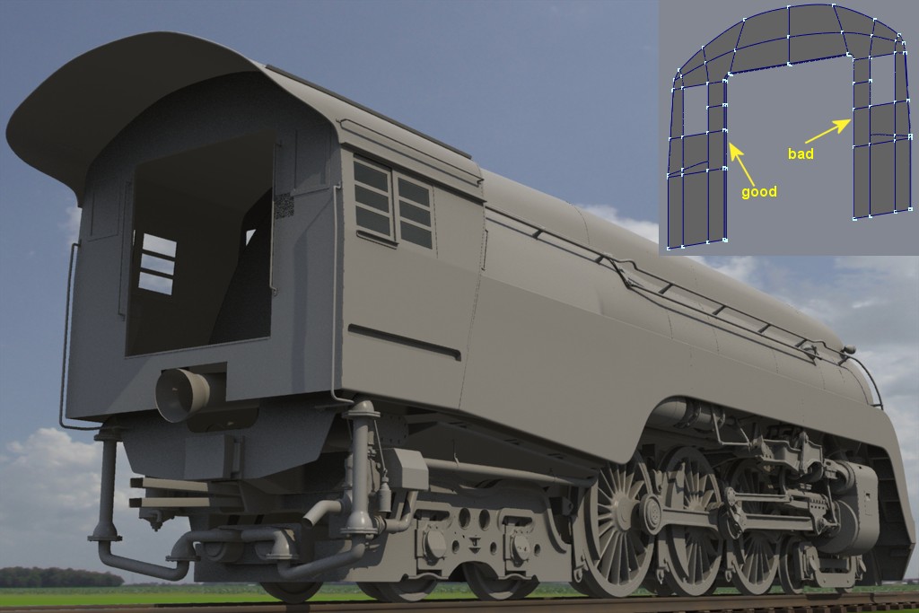
The patch layout to form both sides of the door are mirror images of each other. The algorithm correctly interpolated from the hook around the left corner but not on the right. Oh yeah, I've done that more than a few times! Its the first thing I check (grab a single cp and carefully move it out of the way to see if it has an invisible twin). Not this time. You're probably correct but (full disclosure) all these renders are from v13. In 2009 when I tried opening my usual "outdoor sunny day" project in v15h, global illumination was not working as expected and since A:M is being supported by one programmer working for free in his spare time, glitches such as that send my brain into "make do, work around" mode. And since every one of these granular shadow problems can be solved with increased patch count, that's what I do. Yes, I know, I really should try a more recent v15 but I get easily distracted by building stuff. Thanks for the kind words about the model. For the curious few, this page shows a comparison of the locomotive I did at the turn of the century and the more accurate version I'm currently working on.
-
Good guess, but no. And here's another interesting glitch related to a hook this time. Once again all normals are aimed correctly. I've run into this sort of thing a number of times on this model but I've learned that just because you can use fewer patches doesn't mean you should. Especially in cases like this where I only saved myself a half dozen. False economy.
-
Although there's nothing inherently wrong with assembling a vehicle using action objects, I have found it to be more convenient to build it all as one model. I've only used action objects to build models that are so complex that they are impractically unwieldy in the model window. So I had to sub-divide the object into modelable components that are re-assembled in an action. I'm curious as to what advantage you see in using this technique on a relatively simple model. If you build the Chevy as individual components in a single .mdl file you can later control the actions of each component after you assign bones.