R Reynolds
-
Posts
176 -
Joined
-
Last visited
-
Days Won
47
Content Type
Profiles
Forums
Events
Everything posted by R Reynolds
-
Any particular reason you used sixteen radial cross-sections on the wheel covers and tires? Eight is standard. Similarly, your turn signal cases could have been constructed with four sections. Are you satisfied with the shading/specular reflections from your highly curved 5 point patches; especially the large ones on either side of the wheel well? I typically try to keep them as small and flat as possible.
-
You might find something useful here: Railroad Paint Shop If you want some reference photos or scale line drawings with side and front views, I can send you some scans from my copy of the Steam Locomotive Cyclopedia published by Model Railroader magazine.
-
Even though I don't feel it's my place to criticize the aesthetics of a piece of hardware, I can't buy into the reality of this vehicle with the look of the gold frame reinforcing the canopy. It looks to me like its made of inflated latex sheeting or perhaps manufactured the same way as those padded toilet seats. IMO it looks neither industrial nor military, but does scream Hasbro. But hey, it's your design.
-
Hard to judge with such a dark material. Would you please set the diffuse colour to a lighter shade of grey (e.g. 128,128,128) so I can see more than just the specular reflections? Thanks.
-
Let me know if it doesn't meet your expectations. rivet_head.ZIP
-
FWIW, I find this four patch (2 kb) rivet head model works pretty well. Especially if you apply 100% normal averaging. Let me know if you want a copy.

-
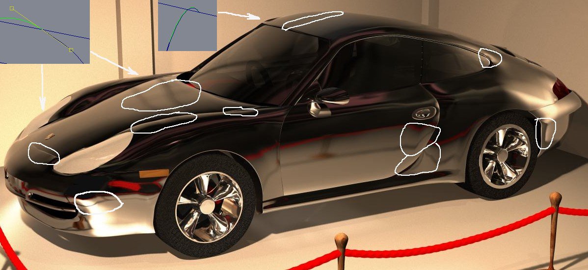
It's almost there but my first impression was "It looks about 6 in. (150 mm) long". I think this is because the bias distortions (aka creases) cause the reflections of the car's surroundings to be distorted beyond what would be seen on full scale sheet metal. I've tried to illustrate my opinion by circling the most obvious examples in the attach image. For newbie education (I'm well aware of your expertise) I've also added wireframes of what usually causes these distortions. The roof line crease should be cured by lifting the central cp out of the small crater it's in. The only exception to my "out-of-scale distortion" observation are the waves in the trailing end of the hood. These look like they could be in a real hood but I doubt the stamping process engineers at Porsche would agree with me. Once again I think these could be improved by making sure both bias handles are on the same side of their spline. I have no idea what's happening to the reflection of the side view mirror but it sure looks peculiar. Did you apply normal averaging (aka porcelain)? My opinion is that it's almost useless for smoothing sheet metal since it bloats trim lines and edges.
-
Thanks to one and all for their kind comments. Xtaz asked; Plymouth copied There's nothing really obvious in the full view shot. But as I've shown in the close-ups, once you get within arm's length you can see all sorts of distortions; usually but not necessarily in the closed loops. The shaded view examples are the most obvious ones but as shown in the last image, there's a number of subtle shifts that you can only see by looking through the wireframe and checking for non-matching splines paths. robcat2075 asked; It looks like it. Go to the bottom of the above link to see a reference photo. I'm not looking forward to modeling the chunk of chrome it's mounted in. Jim Talbot said; You're welcome. John Bigboote asked; To quote from my website "for all intents and purposes I'm building a full scale railroad layout". For a more long winded explanation, visit the following link; Modeling Examples
-
Plymouth WIP Building the round gas cap cut-out in the curved rear fender must have been the most time-consuming modeling I've ever done in A:M. It's still not realistically smooth but I've decided that adequate is sufficient.
-
I don't think bump maps are up to the challenge of simulating such sharp edged features as treads. At least not at an arm's length inspection. However they do work well for the softer sidewall details. Tread pics I've found that the problem with modeling treads with splines is you can't make the sinusoidal edges of the tread edge too sharp (by reducing magnitude) because then the overall curved shape of the tire surface starts to break down into individual facets. After a few weeks of experimentation, the fairly smooth treads shown in the above example were my compromise solution. There is still some creasing but I find it tolerable. As shown in the third example image, I also tried to model the style of tread that has individual, interlocking tread grippers that I found on an adandoned tire in the nearby woods. It avoided the facetting problem but the tire model alone was 2.6Mb. Even I can't justify that level of overkill. If you're still interested I can send you a chunk of modelled tread and you can play with it yourself. BTW; I hope the body of your car is made of a new light weight alloy (styrofoam? ) because your spokes look kinda thin to me.
-
Most impressive. Sort of a stylistic cross between Metropolis and what I've seen so far of Sky Captain and the World of Tomorrow. This God's eye view tends to make it look a bit like a model. Could we see point of view from someone standing at the base of the clock tower? How many individual models did you build? I'm curious to see a wireframe of the structure to the right of the clock tower.
-
Thanks for the compliments, guys. Rodney asked: I'm worried A:P would choke on a 4Mb model. But I may give it a try when its compatible with v10.5. Since A:M v1. Not yet. But it's like eating an elephant, one bite at a time. Mine was in the backyard so I could use natural light for my 16mm movies. mrsl13 asked: Everything except for the sky which is just a picture decaled to a hemi-sphere. robcat asked: Around the turn of the last century they were trying to improve the maximum load that wooden freight cars could carry by adding a truss array of reinforcing iron bars below their floors to strengthen them. As all steel car construction became standard these cars were phased out but some were still in use in the 1930's. This image rock displ is an overhead view of rock_displ.mdl. It's a 9000+ patch model of only the top halves of individual rocks over a 9 x 9 ft. area They all started off as a 4,6 or 8 patch "primitive" which I cut and pasted at random and then tweaked them to fit as tightly as possible (it took a few weeks, on and off). I randomly placed each rock in the vertical direction at one of five heights. Next step was to apply a noisy gradient map so the grey values generally went from 0 to 255 with some random variation to try to simulate smaller detail. I applied this as a displacement map to a flat mesh of 2916 patches representing a a 109 x 109 in. area. I applied a procedural map to the mesh to vary colour on a micro scale. I also applied 33% of the same image as a colour map to get some overall colour variation on a macro scale. In the chor. I tiled copies of this model on 9 ft. centres so one overlaps its neighbours by an inch. It's not obvious in the image but the rocks along each side of the perimeter are only half visible and identical copies so they are perfectly tileable.
-
standard 40 ft. length (circa 1950's) with steel sheathing box car pic
-
box car textures WIP I've been getting more satisfaction from building textures now that I've adjusted my attitude by repeatedly chanting the acronym THWRT (pronounced "thwurt", it stands for "to heck with render times") to overcome my fear of multi-multi-branch materials. I took a chance and mixed modeled rivets (the darker ones) with bump mapped (all the sheet metal rivets) and was pleasantly surprised with the result. I've rationalized their different textures by assuming sheet metal rivets would be made from a different alloy than structural rivets. However the close-up image shows one, not unexpected, hazard to bump maps; the ladder rung's shadow doesn't contour over the rivet head.
-
Good first attempt. Any chance we can get leaves that look less hairy (and diffuse) and more leafy? How far can you push the branching? (i.e. many more and longer branches)
-
Any particular reason you used 24 lathed cross-sections to model the saucer? It looks as though you could've used only 12 and still be able to get the fore and aft cut-outs.
-
There are three links to automotive reference images on this page [url="http://www3.sympatico.ca/rodger.reynolds/auto_tute/auto_tute.htm"]Automotive Modeling Tutorial[/url]
-
This is something I've been putting off doing because I knew just bump maps weren't going to cut it for such exposed and prominent tread lugs. But the worst part was joining all the loose splines for each rotated segment copy. Although I simplified the tread pattern on the real tire, it's still not absolutely crease free and at 3156 it's a bit patch heavy but it should hold up to an arm's length inspection. Still working on materials. [url="http://www.netcore.ca/~reynolds/examples/truck_wheel_WIP.htm"]truck wheel WIP[/url]
-
What sort of ammunition is she using? I'm assuming bullets with phosphorescent heads that illuminate the inside of the barrel.
-
FWIW (but not for a BMW) http://www.netcore.ca/~reynolds/auto_tute/auto_tute.htm
-
Hear, hear! I feel your pain. But everytime I begin cursing 5 pointers, all I have to do to calm myself is to remember modeling in those previous versions that didn't have them.
-
My compliments on a fine example of spline wrangling. Some comments & questions with reference to the attached image: Exhibit A - Dead end splines usually cause creases. Any reason for this arrangement? Exhibit B - It appears to me that this spline can be deleted without seriously affecting the surface shape. Any reason for its presence? Exhibit C - In my v8.5 models, 5 pointers such as this tend to cause problems. Is the version you're using more tolerant or have you applied porcelain.mat? Exhibit D - Is this prime candidate for bias tweaking a 4 or 5 pointer?