R Reynolds
-
Posts
176 -
Joined
-
Last visited
-
Days Won
47
Content Type
Profiles
Forums
Events
Everything posted by R Reynolds
-
All aspiring automobile modelers should pay attention to the relatively high patch density of this great model. Just because you can minimize patch count doesn't mean it's a good idea. It's been my experience that trying to use as few patches as possible eventually bites you in the spline when trying to achieve convincingly smooth automotive surfaces. BTW Stian, where did you get the decal images of the interior surfaces?
-
Would you explain what it is about my attempt at an automotive tutorial that's difficult to understand? Maybe I can clarify it.
-
Absolutely. Assuming you can't find better roto's, you haven't much choice. And what are the chances that your going to pay some penalty because your model isn't an absolutely perfect replica? There can't be that many Batmobile nit-pickers.
-
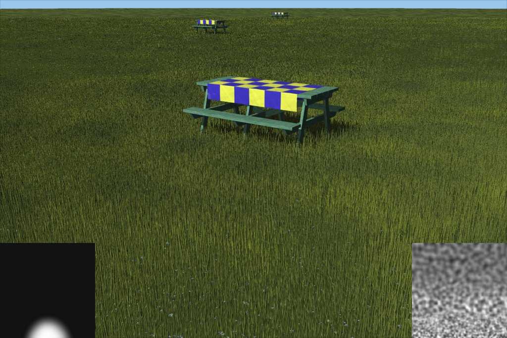
For instance in the attached grass test image, the grey scale image on the left is the density map, you only need higher densities near the camera and can drop of quickly and still look believable. The other grey scale image is the grass length map. The underlying ground patch has a Darktree material called meadows.dsts that I found on the Net. There is no grass growing beyond the farthest picnic table just a simple noise\bump material to try to suggest distant grass.

-
Excellent modeling! Are the tire tread details displacement decals? They're cut so deep they look modeled.
-
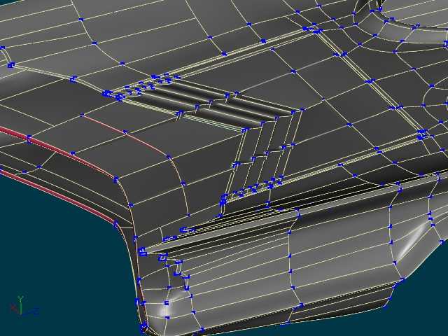
You've been seduced by the desire to keep patch count low. You might get away with increasing the magnitudes as Eric suggests but I would suggest you just bite the bullet and add more splines (see attachment) which will give you much more accurate control over your surfaces.
-
It's coming along nicely. Now that you've done the copy/flip/attach you may want to check for flipped and now incorrect bias signs (especially alphas) that invariably happens after this operation. The best way to find this problem is to closely inspect the wireframe in an orthogonal side view and look at matching splines on both sides of the body that don't have the same shape as intended since they don't have the correct bias sign. My only suggestions for further bias tweaks is the subtle waves in the top of the rear quarter panel, just behind the oval passenger cutouts. There appear to be even smaller waves in the middle of the hood but this waviness might fall within the acceptable range for typical auto sheet metal of the time. Less subtle is the shape of the trailing edge of the hood. It looks a bit puffy to me. You may want to individually isolate the splines on either side of the gap between the hood and the panel at the leading edge of the passenger cutout and check that they follow a smooth, consistent trajectory. The fit and finish around your door gaps look good but I'll warn you to plan ahead for building the interior of the doors. If you decide to extend the exterior surface to build its sides and interior, your lovingly tweaked bias handles will go kerflooey as A:M's internal bias calculations work against you. You have two choices. Extend the existing splines and be resigned to redoing your bias tweaks (my usual choice since it makes for a more realistic model; either that or I'm a sucker for punishment ) or build the interior of the door as a separate model (easier but less accurate). In some ways I consider your Batmobile more impressive than Stian's Bismarck. Sure it's big and has a lot of parts but there aren't a lot of convoluted surface profiles on a battleship. Stick to it!
-
Stian, Early in this thread I made some comment about the size and spacing of your rivets. Having seen your reference images, you may totally ignore my opinion. I'm thoroughly jealous of your resources. I wish everything I wanted to model was this well documented by an obvious fanatic whose willing to post them for free on the Net. Looks like you'll easily beat this guy another Bismarck model who wants to keep his polygon count below 800K. Speaking of the Bismarck images; the catapult for the reconassaince plane looks awfully short, even for a small prop plane. I wonder how many G's did the pilot pull?
-
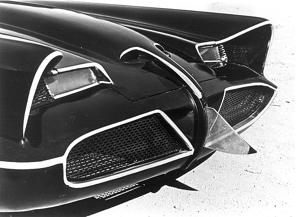
I think you're hurting yourself on a number of levels by making the wheel wells an integral part of the fender panels. First it's not very accurate, especially for a car based on the Ford Futura. This type of bent edge on automotive sheet metal panels is typically about an inch or so and as proof see the attached picture of the Futura concept model and a close-up of the front fender on one of the original Batmobiles. Secondly it makes the modeling of your wheel wells overly patch heavy since they have to share cp's with the contoured fender. I'd suggest you cut them off as I've shown and build much simpler wheel wells as part of the chassis. And build the wheel wells after you install the wheels so you can give them enough clearance.
-
If you're in the mood to really check the smoothness of your surfaces, try the following settings on each group. diffuse colour= 128, 128, 128 specular colour = 255, 255, 255 specular size = 50 specular intensity = 50 Then rotate the surfaces and watch for unexpected changes in the specular highlights.
-
I think Rob is curious as to how you model your rounded corners. Do you peak both sides or leave then smooth?
-
No, not yet. A few years ago Hollywood and the exhibitors finally found the quality/price point where, IMO, what they deliver isn't worth what they charge. (Of course being in my 50's I tend to say that about more and more products). So I'll probably be patient and wait until it hits my satellite dish next summer.
-
If you do find someone who is accomodating enough to photograph his/her car for you, there are a few tips for taking the pictures on this page; Automotive modeling suggestions
-
I was using prototype to mean a typical example of the object which you are going to copy using A:M. Perhaps. For whatever reason the kit manufacturer chose the '49. I couldn't find a kit of the '51. I assumed that the difference between the two models would be insignificant enough that reference images would bridge the changes. Whenever I am toying with the idea of modeling some object; my first priority is to find enough reference images to make the model accurate. If I were in your position and couldn't find enough images of the '51, I'd compromise, buy the kit and build the '49. Either that or start looking for a prototype with better pictures.
-
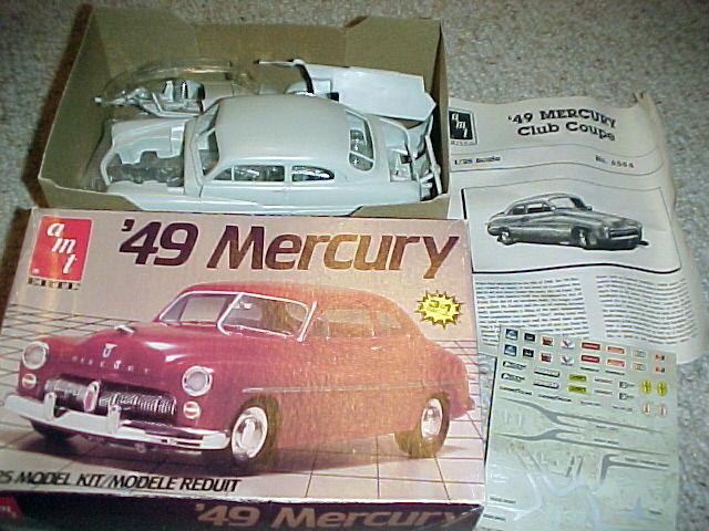
Nice choice of prototype! If you can scrape up an extra $20 and can afford to wait for delivery, I'd suggest you buy the 1/25 scale plastic model of a '49 Mercury (AMT 6594). AMT kits for sale Even if you don't assemble the kit, the individual parts will show you things you could never get from web photos and line drawings. If you assemble the kit (and since it isn't the final "product" you can throw it together with a hot melt glue gun) you can take better roto images than you could ever get from a full sized car. Other than this, Google's your only hope.
-
Beautiful model so far but I think it's counterproductive (from a realism standpoint) to use oversized rivet models on such large centers. Have you considered bump/displacement decals? You can install multiple, accurately scaled and spaced rows along with the lap joint between them with decals like the one attached.
-
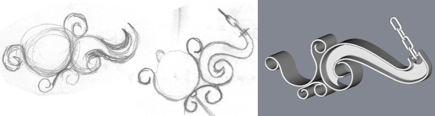
As someone who tends to model real objects, I spend a lot of time looking for reference photos, hopefully but not necessarily rotoscope worthy. At the very least I need a rough sketch to give me an idea of shapes and proportions. The attached image shows the gestation of a chandelier bracket I'm working on.
-
Impressive!
-
I'm curious to see a shot similar to the attachment so I can inspect the wheels.
-
I stumbled across this page while researching something else. You may find them useful. Batmobile pictures The downside is that they might cause you to further re-model for the sake of accuracy. As an example the attached image shows a somewhat different hood than your model.
-
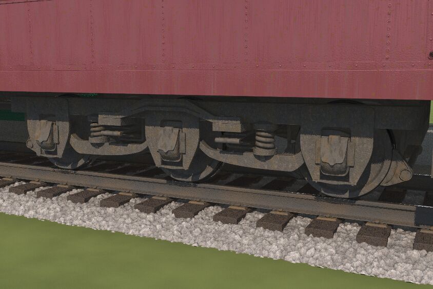
First rate! Any chance of seeing a street level shot showing the bogies (trucks in N. America)? What did you do for prototype drawings/pictures?
-
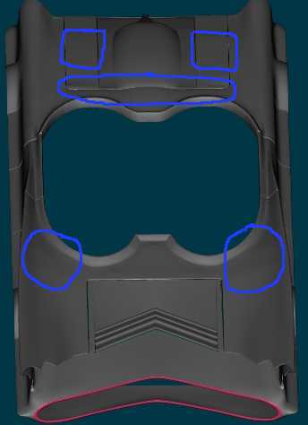
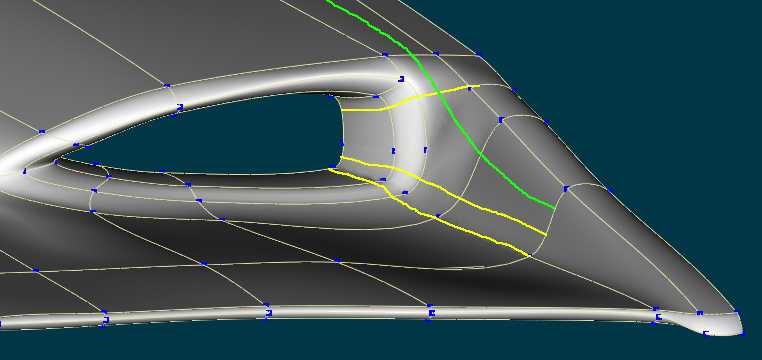
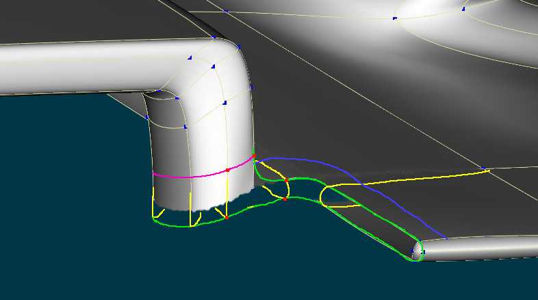
Here's some suggestions. On the scoop I think you're being too stingy with splines. If it were me, I would definitely add the yellow splines to give me more control over the shape of the scoop and the transition into the central ridge. The green spline is optional but I would probably put it in to reduce the size of the 5 pointers and improve their smoothness. On the hood I've found this is to be a good layout for such an inside corner. The downside is it produces a huge 5 pointer on the hood which may cause problems. The blue spline is added to isolate this 5 pointer from the rounded edge and improve the chances that it stays smooth. The smaller 5 pointer (outlined by red cp's) could prove to be pretty ugly but it's small and I'd wager this isn't that smooth on the prototype.
-
It's always tempting to begin a mechanical model by tackling the simple areas because you get quick gratification (it's like the Dark Side, "easier...more seductive") but in the case of AM modeling I think one might be better off starting with the hardest (most dense mesh) parts. In the case of the hood, that would be its corners, the air intake holes and the folds around the headlights. I'd suggest you model those patches first and then you can reduce splines as you get into the smoother areas.
-
FWIW, I agree with you on this one but later on you show an image with a very wide open mesh. I would suggest that you stick with 6 in. patches or smaller. Up front, don't worry about tweaking bias to get smooth surfaces, worry about getting all the patches you need to get an accurate model. Put in cp's as though you didn't have control of bias values; that every shape change needed a new cp. IMO, once you have the overall shape finished but not smooth it's much easier to delete extra splines and tweak bias as necessary. It's been my experience that the way A:M modifies spline shape when inserting/moving cp's and sometimes messes up the signs of copied and or flipped bias values means that it's counterproductive to worry about bias values at all until you're completely satisfied with the general shape of the complete mesh.
-
I realize I'm really late to this thread but here's a quick suggestion.