Search the Community
Showing results for 'snap to surface'.
-
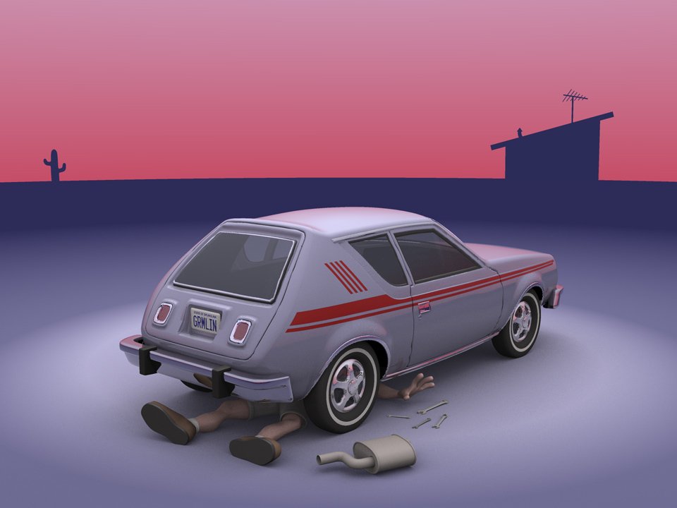
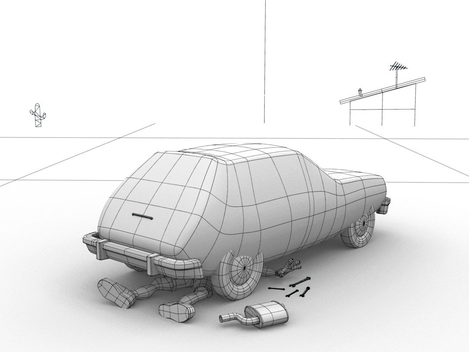
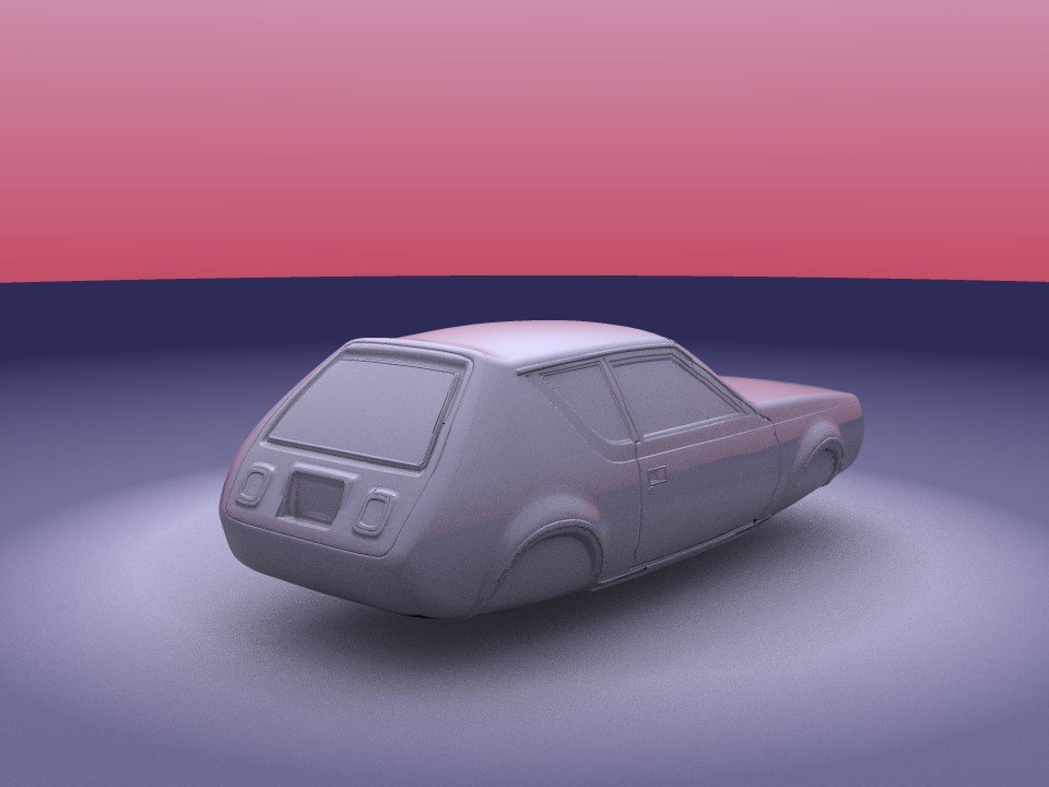
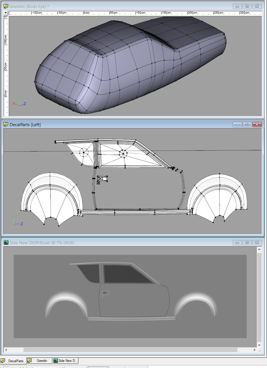
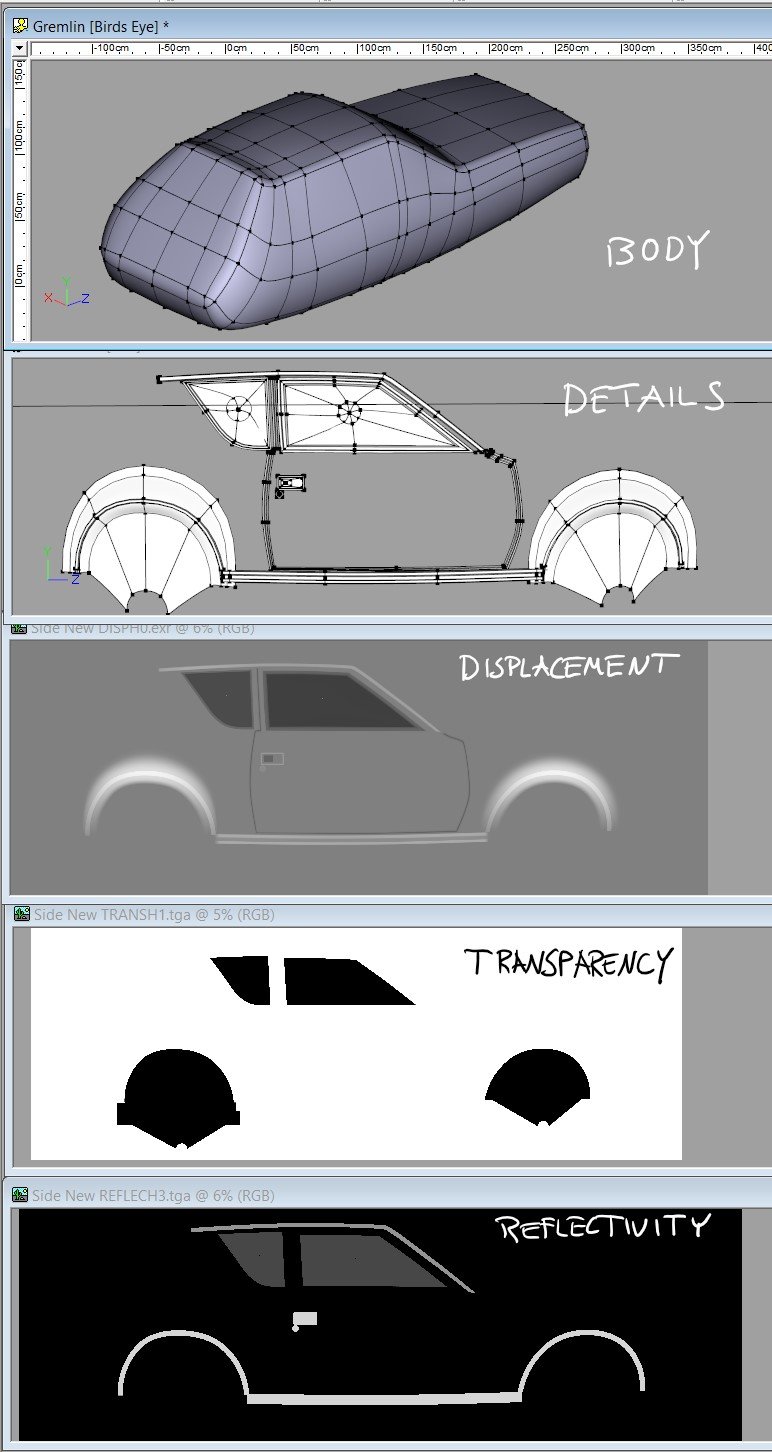
My "Planes Trains Automobiles" Contest entry was an experiment in displacement mapping... The body of the car is just a simple spline form... All the surface details... the doors, the handles, the windows, the rubber and chrome trim... that is all made with displacement maps. There isn't an easy way to manually paint such maps in a paint program but it was easy to model the shapes on a flat plane. I put a white-to-black gradient on them and shot the arrangement with an orthogonal camera. That render to OpenEXR format was applied to the body to be the displacement map. I made maps that way for the front and back details also... I recolored the patches of that details model with white, gray and black to render versions of the map for Transparency and Reflectivity... A turn-around of an earlier WIP version of the car... 155Lefts_3500.mp4

-
Nancy is correct. Snap to Surface works much better in a Choreography. AND it works much better when you are working on top of an .obj prop. However, in this case, the mesh is so dense, you'd quickly lose track of the splines. A snap to cp feature the works similar to the "Snap to Grid" would be ideal.
-
I was not very successful with snap to surface (but I tried awhile back) - but: 1) I suspect the model that I was trying to snap to did not have a dense enough mesh, and 2) I believe I was a little bit more successful (it's been awhile) when I tried to snap patches (4 cps) rather than just one cp. And 3) perhaps it worked better in the chor (rather than modeling window, or pose?) - with the model being snapped to was imported as a prop, maybe? As I said - I can't remember, as I became impatient, and really didn't have a use for this, other than trying it out. At some point I thought I might want to model a rough 3D rotoscope model first in A:M (made of spheres, primitives), and then use that to guide my modeling for a more detailed model. I didn't/don't have any high density polygon models that I wanted to bring into A:M from any other program, as it seems that's what this feature is more suited. s2s did seem very touchy to me.
-
Very cool – thanks a lot Steffen, Jason and all the Beta testers – very well done . One of the new features "Snap Bias Handlers to Grid" is shown in this video-tutorial: https://www.patchwork3d.de/snap-bias-to-grid-195-en ...and another one I covered in a video is "Remove internal patches": https://www.patchwork3d.de/remove-internal-patches-196-en Hope you can see some of the potential of those features... there are a lot more to discover of cause as you can see from that LONG list . Best wishes *Fuchur* PS: Sorry for the heavy accent in the video tutorials... I am not a native speaker .
-
Something you'll love in v17 is the Spline to Surface tool. With it you can model on top of an existing construct and even change/replace that underlying construct too. It's also great for modeling extra (unconnected) details right on top of a model. Note to those using Spline to Surface in a Modeling Window: I find it best to lock down the template after drawing a small 2 CP spline using the Lock key/icon. Then delete that spline and model over the locked geometry. Of course... make sure you select the Spline to Surface icon before splining or else you'll model a lot of geometry that isn't on the intended surface. Doh! I hate it when I do that. Snap to Surface, not Spline to Surface Rodney, but other than that: Yes, good suggestions. See you *Fuchur*
-
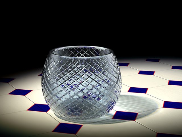
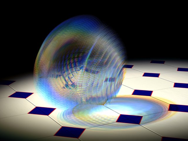
Further development of our live Answer Time discussion Saturday... these use a displacement map to create the surface detail. Whoops!
-
A:M v16 (and up) utilizes multi-cores using OpenML for Finding Normals and a few other functions (where it makes sense). Like that today you can handle more patches in a single model than before. It highly depends on your core-amount and the power of your system and yes you will still run into the problem somewhere. Best is to avoid that by assembling together multiple models in the chor. The new Snap-To-Surface-Feature in v17 maybe helpful there too. There are many changes from v13 on. I am not totally sure what was in v13, but these are the bigger and "newer" features in A:M (not in chronological order): - Speedimprovements (especially from v15 to v16 but also for v17) for both Windows and Mac. (windows-computers seem to perform a little better so). - Netrenderer now included with 4 cores for free and addtional cores that can be bought seperatly for a very reasonable price). - IBL, Ambient Occlusion (with Transparency-Support) and FastAO (> Plugin, actually called "FakeAO" which is very fast, the newest one even can use the GPU-power, but even the CPU-version takes only a few seconds to render with) - Fluid-Particles - Hair-Shaders (additional to the standard-hair-system) - HDRI-Rendering with Buffer-Output - STL-Export (for example used by 3d-printers) - MDD-Animation-Data-Export (to export vertexed-based animation). > for example to get animation-data to Modo) - RenderPresets to share render-settings in an easy way. - Selection-Filters for easier selection. - SubSurfaceDisplacement (I am not sure if this is really new for v13 or if it was included there already). - Bake Surface (> bake Surface-attributes to decals so they may render faster. Includes an AutoUnwrap-Algorithm which is best to be used with 3d-Painter) - Newton Physics (I am not sure if this is really new for v13 or if it was included there already, but they have been improved in v15 if I am not wrong). - 2008 rig, face rig, lightrig - Snap-to-Surface (in A:M v17) - A:M Answers (in A:M v17) - UV-Editor-Improvements (in A:M v17) ... endless smaller and possible bigger improvements I can't remember right now. See you *Fuchur*
-

Is there anyway to match the camera perspective to a photo?
rijklau replied to rijklau's topic in Open Forum
They might just randomly snap the photo from shop display and said, I want it to have a 25.4 cm base. Or even worse, they just copy it from a magazine. -
I saw 4k raw video being edited on a surface pro. Now would I want to try to edit video that way, no. But it shows the power. As a user of both the ipad and surface both are very useful. but I have a very heavy laptop and the new surface appeals to me . One thing I am thinking about is sound editing. Surface has the windows software audio editing. It would be nice to use the surface and record the voice overs and edit them as they are recorded by something other than the big laptop I have. Plus for larger screen sizes the surface has an HDMI out adapter for large screen and USB for keyboard and mouse that could be used in the office environment. Steve
-
Welcome back, Al! Remember, that ease comes because it take many fewer CPs to make a shape in A:M than vertices in a polygon modeler. 1) Keyboard 4 will constrain a CP to the direction of the spline at the point it starts from. If the spline is curved you will change the shape of the curve as you drag it but I use this quite a bit to adust CPs in a mesh, none-the-less. Also... 5 will constrain the CP to motion perpendicular to the original spline. 6 will constrain it to motion perpendicular to the surface. 2) the CutPlane plugin can do this in simpler situations. It can insert a spline ring (or unsplined CPs) at the intersection of the cutting plane with a mesh. 3) I think so? 4) You may define any res you want, limited only by your RAM and patience. 5) The Snap To Surface tool allows you to draw new splines on the surface of another shape as a guide. Informally called "retopolgy" on the forum. 6) That should be fine. That's way more than I have. 7) Besides the goat?
-
It's possible you have something called "snap to surface" on. This new feature is for drawing splines/resplining on an imported polygon prop. Ray traced lights are slow, but you can get accurate fuzzy ray-traced lights by setting the light "width" wider and increasing the "rays" parameter. Use the narrowest width and fewest rays you can get by without grainy looking shadows.
-
A quick fix update . As of v16b, Shift and select "snap to grid" will only snap the pivot point to the grid. The older set up snapped both the pivot and the CP. To only snap the CP's just use the "snap to grid" with the CP's selected.
-
Are you baking your particles? As far as my approach to geometry based hair there are quite a few tutorials on cloth so it might be best to point you to those. In the meantime I'll offer this: ---------------------------------------------------------------------------------------------------------------------------- Cloth Simulation ---------------------------------------------------------------------------------------------------------------------------- The basic approach is: Create two materials: 1 - Cloth 2 - Cloth Deflector 3 - Apply those to meshes and then simulate Rename these materials as Cloth and ClothDeflector or something easier to find later. (A:M doesn't automatically name them anything particularly useful so we have to do that) Create the mesh that you will use as hair, fire, smoke or whatever you will be attempting to create via the cloth simulation. Considerations: When dealing with cloth simulation there are several 'tricks' to getting it to perform with maximum control. Here are a few: - Use Named Groups! By naming Groups we can not only better understand and organize we can layer in effects. For instance, having a group of objects that will serve to deflect the cloth (i.e. it has the Deflector Material applied to it) that is invisible (turn its surface property to Transparent=100%). In this way you can channel and direct the simulation in interesting ways. - Consider leaving dangling splines outside of the area to be simulated. These will ground the cloth to something stable that will not be directly effected by the simulation. In the case of hair these might be below the surface of the 'skin' that the hair will appear from. I try to select these dangling splines and name them something like 'base' so that they can be modified later. - Consider the distance from each object you've created. Overlapping meshes will cause the cloth simulation to error out because it can't properly calculate the interactions and directions. (i.e. it doesn't know which way is up because we've confused it by having interpenetrating meshes) - Consider saving out/exporting a frame of the animated simulation as a separate model. In this way you could generate thousands of resources simply by launching one simulation. We then can animate those separately or... simulate them again in other ways. ---------------------------------------------------------------------------------------------------------------------------- Forces ---------------------------------------------------------------------------------------------------------------------------- Adding forces (via Right Click/Add/Force) in an Action or Choreography allows us to push and pull geometry around in a dynamic way. This is especially useful for cloth simulation. We can hide or lock objects or add invisible objects in between the force and their location to 'protect' them from being effected in the same way as those areas that are fully effected. ---------------------------------------------------------------------------------------------------------------------------- Render As Lines (RAL) ---------------------------------------------------------------------------------------------------------------------------- Render As Lines is considerably more basic than cloth simulation and is not as versatile because there are no patches. It is important to note however that RAL can and generally should be augmented by the use of patches. For example you might have a cool looking robot and just add some detailed lines over the top of the robot's mesh to add the appearance of additional details. With v17s new 'Snap to Surface' features adding splines to the surface of a model is easy whereas before we had to painstakingly turn our models around or view them from multiple angles simultaneously to make sure the lines were on the surface. In my estimation the secret to RAL is using Named Groups to layer in of additional properties on the same splines/shapes. Using a little roughness and then adjusting the scale of that roughness can create some very interesting effects. Because RAL does generate some rendering artifacts on occasion it's often best to take this one step further and convert the splines to geometrical (patch rendering) shapes. This is trivial and easy to do with use of the Sweeper plugin. Just draw a little spline shape (say three CPs connected) and name it as a Named Group (because I will delete it later I often name mine, "Use Me". Then I can easily find it in the Sweeper dialogue. ---------------------------------------------------------------------------------------------------------------------------- Sweeper plugin ---------------------------------------------------------------------------------------------------------------------------- The Basic Steps to use Sweeper: Create the splines you wish to sweep (It's best to Name this as a Group although technically it isn't necessary) Create the shape or object you wish to sweep (name this Group) Select the splines you wish to sweep Right Click and go to Plugins/Sweeper Select the shape you wish to sweep from the list of Named Groups in the drop down menu Adjust other parameters as necessary Launch the sweep The swept shape will automatically be named so it will be easy to move away from the splines used to create it. That original spline can then be adjusted or used for additional sweeping or discarded. If the swept object isn't to your liking simply delete it and sweep again with different settings. Move them to the side if you wish to compare multiple sweeps with different settings. That is a basic primer for the areas under consideration. As I mentioned before, I haven't actually pressed into the classic use of decalled hair that is then cloth simulated. This is especially powerful because we can use Patch Images (with all of their various Image Types) to layer in the hair. That hair can then be further animated/simulated. It should also be noted that once we've got the geobased system in place we can further augment that with particles based effects (to include but not necessarily requiring particle hair). For instance, geobased hair might be further enhanced through the use of sprites or blobby effects. The general premise being to accomplish what we can with simple geometry and use particles to achieve what cannot be easily achieved complex geometry and interactions which is what particles attempt to simulate.
-
This is getting hard... okay so what I can remember is: Version 15 (2008) Liquids, Baked Surface (bake materials and decals to decals), Hash Animation:Master Realtime (HA:MR) integration (no longer available in newer versions) Version 16 (2011) 64-bit Version, Netrenderer-integration with Multicore-support, 3d connexion device support, OBJ-MDD-Animation-Export, overall performance-boost Version 17 (2012) Snap to Surface (Retopology-Tool), Animation:Master Answers, SSE4 instruction support, Create your own "Support"-page, Animate-Mode indicator, Improved Cloth-Simulation with Hi-res Simulation, STL-Export (with resolutionlevels up to 64 instead of formerly 16 polygones per patch) You can find tutorials for Snap To Surface on my website. (see below) There is very likely much much more that I am not aware of now... See you *Fuchur*
-
How do I stop Windows 10 from resizing windows when i drag them to another monitor? Online advice says to turn off "Snap" but that didn't solve it.
-

Basic workflow in assigning properties to objects and shortcuts
robcat2075 replied to dblhelix's topic in New Users
Almost everything in A:M has "properties" Make a new model and it has many default properties you can see by selecting the model in the "Objects " folder and then looking in the Properties window. You an change those default props. ForEx, you can change the surface color from white to red or the surface transparency from 0 to 50% If you make a group in that model it gets default props too, but most will be "not Set". Group props overide Object Props but if they are "not set" they let the Object prop for that thing pass thru. If my Object surface color is set to red and a group on that model has surface color "not set" then the surface in that group will still appear red. But if the group's surfColor is set to green then the part of that model in that group will be green, everything not in that group will still be red. If I had dropped a Material on that object that set "surface color" to yellow, that would override the Object's red surface color but not the Group's green surface color. Any parameter set at the group level will override a parameter set at the object level, even in if it was a Material at the object level that was controlling the parameter. However, If I had instead dropped that Yellow Material on the Group, that would override the group's Green setting with the Material's Yellow setting. The part o the Object not in that group would still be its original Red color. That Yellow Material has properties too. If I go up to the Materials folder and edit that color setting from yellow to purple, the Group that has that material on it will change to Purple as will any other models or groups that have that Material working on them. if I click on the Material where it appears under the Group (really a "shortcut to") I will see properties in the Properties window that look just like the Properties I saw when i was editing the Material in the Material folder. If I edit the Yellow to Purple here it will only change the one instance of the material on this group. The original material in the Materials folder still has its original Yellow setting and anywhere else it is used it still makes Yellow. When we put that Object in a chor we get yet another layer of ability to over ride. When you "Show More than Drivers" you can see all the groups and materials the object has and you can fool with the parameters again in yet anothe set of property windows that initially look just like the property windows you saw at the group or object level. Why would you want to do this in the chor? Because in the chor you can change these settings over time. You could animate the material to change from Yellow to Purple to Green. You could animate a property that hadn't' been set at all in the object previously like the XYZ position of a material on a group So ... Objects have properties Materials have properties Materials properties override Object properties Group Properties overrides Material on Object properties Material on Group overrides Group properties You can change any of these in the chor, it won't change the original saved model or material. The different kinds of maps don't usually have priority over each other since they control different surface attributes. One exception is you can't have a displacement map and a bump map since displacement maps steal the bump map shading process. -
I think the only thing you possibly did "wrong" as it were was to not start by opening a new On/Off pose to set things up in first. But the rest I think has shown up two possible bugs; 1: A bone set to be a Boolean Cutter won't track a surface when it is then constrained to a surface by a Surface Constraint. 2: If the Aiming bone in a Surface Constraint has an additional Aim At constraint applied to it, so that it follows/is controlled by a target null. The bone that was constrained to the surface in this Surface Constraint setup stops moving. I can submit this as a bug report, unless any one else here thinks I have miss evaluated some aspect of this.
-
I will try to explain a couple things but there are so many angles to cover that it might take a few Q and A to get all information out. HDRI are excellent for reflections. Much better than LDRI especially on colored reflective surfaces. But getting the correct light range right can be tricky. First, here is a procedure I use to cap the range of HDRI files: This works in Photoshop CS but it might be different for CS2 and/or CS3 because I know that Adobe now can process HDRI files directely without the need to convert them. So say, I want to cap my HDRI file to +2f-stops. I open the file and in the EXR preview dialog, I drop the exposure by -2f-stops (and make sure the gamma is set to 1). When loaded, the file is converted to 16 bits. I then save the file back as an EXR format. Photoshop asks me is I want to recompensate for the dropped f-stop (or something like that). I click Yes and voilà. THe EXR file have now a maximum of 2 f-stops of dynamic range. In version of Photoshop that can process HDRI files without conversion, I would probably need to drop the f-stop, then save the file to a 16-bits format, then reload that 16-bits format, raise the f-stop and then save back to exr again to get the same result. Now that you know how to cap the dynamic range, here is why you would want to do that. On highly reflective surfaces, large dynamic range will produce strong aliasing if the surface is highly specular or will tend to produce noise of bright pixels if the surface is softly reflective. So you want to drop the dynamic range as much as possible to reduce those aliasing effects. The problem is when you also have low reflective surfaces in the same scene. Painted surface such as the plane in your scene. You want to keep enough dynamic range so the reflections on the plane look right. It is a wuestion of finding how much dynamic range is enough for that plane and not too much for the gladiator armor and the plane exhaust pipes. In this scene, we have 4 different types of surfaces: 1) non-reflective surface - those we don't need to bother about. 2) the plane exhaust pipes - they are highly reflective and highly specular. 3) the gladiator armor - it is highly reflective but lowly specular and 4) the plane red paint - it is relatively highly specular but have a medium reflectivity due to the paint. The surface characteristic that will drive our decision of how much dynamic range we need is the surface with the lowest reflectivity. In this scene, that would be the plane red paint. There are some rule of thumbs to help figure the highest dynamic range that a scene would require but it might also be easier to find that by trial and error by saving several version of the EXR file with differently capped ranges and just try them all until the optimal one if decided upon. The rule of thumb is this: Take your darkest reflective surface color, here that would be the plane red paint. Check its color. This is the simplified reflectance of the surface. Say the color is RGB( 100, 30, 30). 255/100 = 2.55 meaning that you need 2.5 more light in your HDRI file so you can probably get an acceptable result with +2 f-stops or even +1.5 f-stops. But for optimal results, you need to take the lowest of the RGB component reflectance so 255/30 = 8.5 so a +3 f-stop would work. Now I did a little magic to get to 3 f-stops. Every f-stop step multiplies the amount of light by a factor of 2. +1 f-stop = 2 times more light. +2 f-stops = 4 times more light and +3 f-stops = 8 times more light which is pretty near 8.5. And, of course, +4 f-stops = 16, then 32, 64, 128, 256, 512, 1024, ... When working with HDRI files and reflections, you will most certainly need to increase the samplings in your render to get rid of aliasing artefacts that HDRI tends to produce. That is the nature of the beast. For highly specular, highly reflective surfaces you will most probably need to increase the number of passes in your render. For lowly specular (soft reflective) and highly reflective surface, you will need to increase the soft reflection's "Quality" property in the render panel. Finally, when working with HDRI files for reflections, let the surface color (reflectance) do the reflectvity work. That means set the surface reflectivity to 100%, reflection filter to 100%, reflective blend to 100% and the reflectivity falloff to 0. And use specularity size property to control the reflection softness.
-
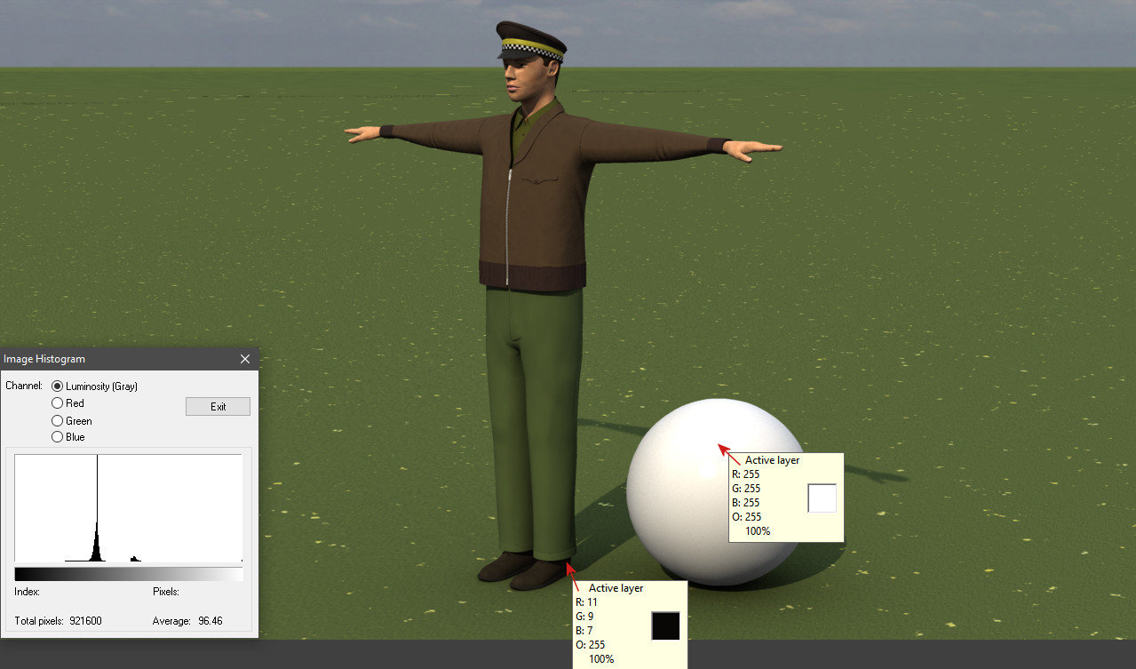
I remember going down this road with you before when I submitted my contest image. I was able to reproduce your monitor photo results almost exactly with my image also displayed beside a calibration image. But it's not like I'm going out of my way to produce dark images, it just depends on the subject matter because my lighting setup never changes. The render shows the unlit interior of a diner on a sunny day. The first attached image shows the driver of a cab (partially reflected in the diner's window) standing outside using the same sunny day lighting. Next to him is my reference white sphere. The RGB value on the sphere's surface facing the sun is 255, 255, 255 and the surrounding area somewhat saturated as I suspect it would be to your eye. The RGB value on his shadowed dark brown shoe is 11, 9, 7, so just barely visible. I chose my lighting intensities to achieve this dynamic range. All my materials' colour values are chosen by how they work when they're sitting outside in the sun next to my reference sphere. The second attachment shows the cab driver next to the calibration image on my monitor. The increased contrast comes from the imager in my cheap phone. Would you prefer to see the first Netrender image of the cab driver? As you can see, it's histogram is pretty limited as well. Perhaps I should take the monitor calibration image, decal it to a surface and render that?
-
DJ added this to his report: Requested Tools: 1. Snap to intersection. (with a button instead of a key so you can turn it on and off) 2. Set "Y" key to snap to midpoint of line as in the model window. 3. Mouse right click and drag to select is not available and would be handy. 4. Distortions Box as in model window. My initial thought is to consider if these features already exist for Snap to Surface workflow within a Modeling window. This provides a framework from which to study and better understand the workflow with Props in the Chor window. The image DJ provided isn't exactly clear with regard to what he is after: Image Link But Fuchur helped determine what he was after: Fuchur asked: DJ responded: This appears to be a new feature request and not just an enhancement.
-
I've thought of one more mistake I made... At 4:51 we see the SHIFT options panel for Bake Surface. I should have set "margins" to 0 so that the tile for each patch wasn't padded with an extra pixel. One pixel wasn't highly noticeable, but zero would have been correct.
-
Basically, anything that artificially brightens the surface will negate the darkening effect of shadows and true Ambiance Occlusion In A:M Materials and Surface Properties and Plugin Shaders, "Ambience" generally refers to things that artificially brighten the surface with a color and therefore don't show shadowing effects or AO as much as they might. other wise. If you modeled a Flourescent light tube that was suposed to look ON you would set it's surface ambiance to 100% so any shadow cast on it would not be visible. This does not make the tube surface emit any light of its own but it does stop it from shading like a regular unlit surface. The "ambiance" term is confusing but it came into use for this sort of artificial lightening long before "real" ambiance occlusion in renders was possible. ––––––––––––––––––––––––––––––- Camera: Global Ambiance (%) artificially brightens all surfaces Camera/Render Options: Ambiance Occlusion (On/Off) you need this ON for AO effects Occlusion Sampling (%) higher % means less grain in AO shadows Transparent AO (On/Off) ON will prevent transparent objects from casting occlusion shadows These are artificial brighteners: Camera/Render Options: Plugin Shaders (On/Off) Ambiance Render Shader (shader) Ambiance Color (Color) These are artificial brighteners: Material: Ambiance color (color) Ambiance Intensity (%) Ambiance Blend (%) Ambiance Render Shader (shader) These are part of the true ambiance occlusion effect: Choreographies/Choreographie1: Global Ambiance Type (Color) Ambiance Color The color of the all-around environmental light that is shined on all objects Ambiance Intensity (%) strength of that all-around environmental light Ambiance Occlusion (%) strength of the occlusion shadowing. Higher is darker. I'll note that Yves Poissant, who wrote A:M ambiance occlusion effect, regards AO as a lighting effect rather than a shadowing effect (as I have characterized it above) and I'm sure that as far as the software works internally, he is correct in describing it that way. I'll also note that for almost all fo these properties, if you have v17 or later, you can on most of the properties and choose "display help" to get the tech ref description of the property's meaning.
-
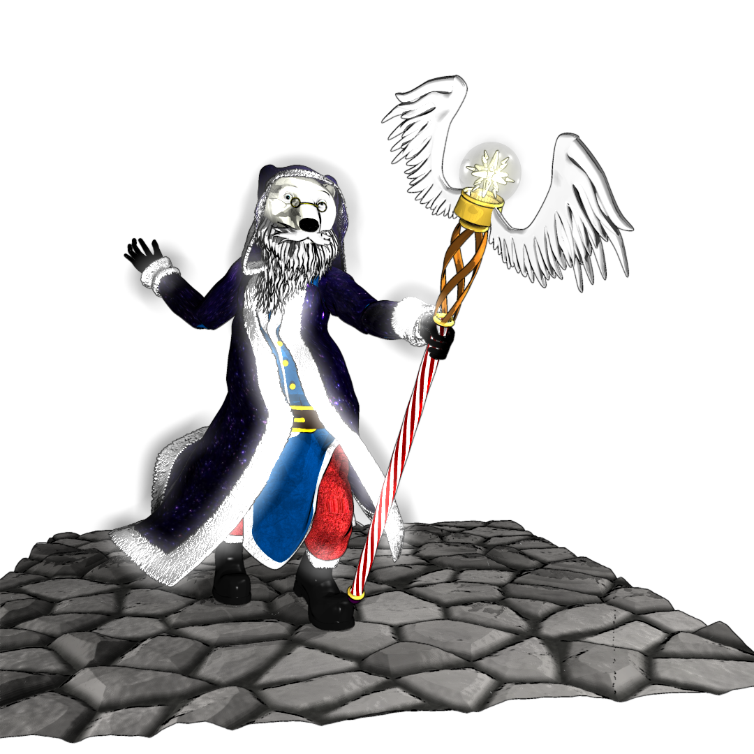
Done some more work on Ursa. Finished rigging his cloak (except the hood) and added his staff (The staff of the north). I set the star fragments in the end of the staff to glow and tried to do a render. But for some reason, even though the star is the only thing in the scene set to glow, A:M is making the fur trim of the cloak glow as well. I even went into the surface settings of the fur and set glow to off, and the group that the fur material is assigned to and set it's glow property to off and the fur is still glowing. Think it might be a bug.
-
There is no cheating and if booleans or cookie cutters work go for it. However I was thinking more along the lines of extruding. Imagine you created a perfectly smooth curved spline that defined the top edge of the helmet , above the eyes and nose. By extruding and scaling/rotating that spline from a specific origin point you can define those large areas that need to be smooth. If you plan carefully ahead of time this extruded spline can even have enough points included to account for creating the eye and nose pieces or you can use the "shift" key to add points without disturbing the curve of the spline. I love that shift key when adding points. EDIT: Check out the tutorial "Adding Control Points" (the fourth one) Done right you can stitch in things very nicely without disturbing a smooth shape. The irregular splines of the eyes and nose could be stitched in this way and those splines carefully stitched up the surface to hooks. The key is maintaining the spline "flow". If you dead-end a spline hook "too soon" it causes a bump or crease. Try hooking it further back. If the cross section of splines is smooth, carefully stitching in splines using the shift key when adding points will not disturb the smoothness. This model is in a category I call "mechanical" or "fixed" or "non-organic". It doesn't move. This is a bonus because you can do what ever is needed to maintain the smoothness without worrying later if point motion will cause bumps or creases. There is no point motion (unless you put in dents with an action). That's another key thing... low patch count (you have that already but it's worth mentioning) the lower the spline count the easier to keep things smooth. Another trick is to NOT move individual points as much as possible. Only rotate or scale using a whole spline cross section or the whole model and the distortion box grid thingy. You could even distort a high patch sphere into the basic shape of the helmet using this technique, then punch in eye and nose shapes. Let's say a cross section spline needs to move up higher for some reason, or a set of points needs to move up, don't try to move each point, find some way to rotate that whole spline so the splines maintain smoothness, or even stitch in a new set of splines (with the shift key of course). I am not an expert in this kind of mechanical modeling by a long shot, so many others can do it so easily it seems, car models, beautiful curved surfaces. It's hard to explain... when you need a smooth curved surface the trick is to either model it that way using extrusions to maintain the flow of splines or global distortions to get the shape you want. Distortions that modify the whole shape so you are less likely to get bumps. If you need to add spline density to an already smooth surface make sure you use the "shift" key with the add point key. If your patch count is low it can be easier to nudge points to smooth things out. I've done that before. As I said it can be a bit tricky and tedious but you can smooth a curved surface with careful nudging. I wish I could explain it better. Maybe this is a subconscious thing from using AM for so long. One more thing, and this is just my humble opinion... perfection has flaws. Even what you think should be absolutely smooth... in real life there are flaws, slight imperfections to catch the light and break up the surface. A perfectly smooth or flat surface just... doesn't look real to me. If you use any kind of materials or decals to break up the surface or give it some kind of texture this can also hide "flaws" in the surface. Don't forget as well... how long is the object on screen? If it is in motion or part of an action sequence the flaws might never be seen at all. Just a thought. EDIT: Adding thickness to the edges. Your helmet appears to have thickness. Thickness can be simple, just extrude an extra set of splines on the edges of the open surface and "fold" them back inside creating an illusion of thickness with out all the fuss. I used that technique on some parts of my terminator model. There is really no need to model an entire interior surface if it is not needed. Maybe in the case of the helmet it might be necessary. the trick then would be to just copy the whole helmet and scale/distort it to fit inside and connect it at the edges. -vern
-
Playing with the Planet material combiner, here is some info: (Looks like I will have to isolate some of these to see what they really do) Feature Size is how large the features are. This is not keyed to how large the model or patches are, so a "physically" large model will need larger values to get actual land masses and not a whole mess of tiny islands. The number of patches has no bearing on the calculations, in fact my station renders the same surface with 64 patches as it did with hundreds. Polar Distance is what the ice caps cover. It is the distance from the equator in cm, a value of 0 turns this off. It appears to be along the surface, not the y-axis. It really should have been an angular measure, as the icecap would depend on how the planet rotates in relation to its orbit; a percentage would heve worked too. As a reference, if you set your PD = to the planets radius you get about a 31 degree coverage. Water primarily affects the elevation of the water. Not sure whether it is a percentage of the amplitude, but it is easiest to treat it as such. The best range seems to fall between 20 and 80; below 20 is barren and over 80 is waterworld. This does affect vegetation and snowcap generation. Bump Strength is surface roughness, as a percent, as is standard in AM Ice is a percentage of coverage to the equator. It has 2 big effects, adding ice to snowcaps and ice to icecaps. A value of 0 turns it off. Frequency Factor is similar to roughness, it appears to be the underlying surface that is modified by roughness, amplitude, and octaves. Amplitude Factor is a percentage. Appears to act like roughness or frequency factor. Octaves alters the waves generated by Frequency and Amplitude Noise Factor adds chaos to some of the other generators, it is most noticable in Polar Distance and Ice. Seed is used to generate the terrain and allows the terrain to be generated in the same way with a certain selection of settings. Offset is a percent, looks like it shifts the median up and down, affecting terrain generation. Mottle Size affects how fine or coarse the generated color map is Higher numbers mean larger clumps means coarser, lower is opposite Mottle Magnitude ?? it is a percentage Depth Noise another percentage, uses the terrain that is underwater to affect the shading of the water. Max Depth caps the values for water depth? Snow the last percentage. Affects snow coverage, works in conjunction with Polar Distance and Ice to provide coverage The material does not generate a displacement map, and in most cases I would agree that it would be overkill, and I may just go with bump maps after I block my shots. Wish it had a seasonal adjustment, thought that was what snow was going to do, but no. A seasonal would shift the north and south hemispheres in opposition, with the middle being spring/fall, one end would have summer in the north and winter in the south, the oppositer end would swap the seasons. This can be done manually, actually, if you seperate your north and south hemispheres and apply a copy of the materials to each, you can shift your snow/ice coverage and move your icecap towards the equator. Now to bake it.