NancyGormezano
-
Posts
7,863 -
Joined
-
Last visited
-
Days Won
15
Content Type
Profiles
Forums
Events
Everything posted by NancyGormezano
-
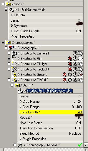
Yes, cycle length and chor range are tied together, along with repeat in all versions. If you only want an action to occur for 100 frames in the chor, then set your action length in the chor to 100, repeat to 1, or length to 50, repeat 2, or length to 25, repeat 4, or length to 10 repeat to 10, etc. Depending on the speed you want for the walk.
-
Yes - you can create your action at any length - and then in the chor, after you've inserted it at the correct place, change the length of the action - essentially speed up or slow down to suit your needs. (I suspect you might not be able to have stride length set however - not sure - did not verify) EDIT - just verified - seems to work ok with stride length

-
For your objects that you want to be front projected & "catch the shadows" - you could turn on flat shaded and turn off cast shadows. Both the ground plane & box in this chor are front projected objects
-
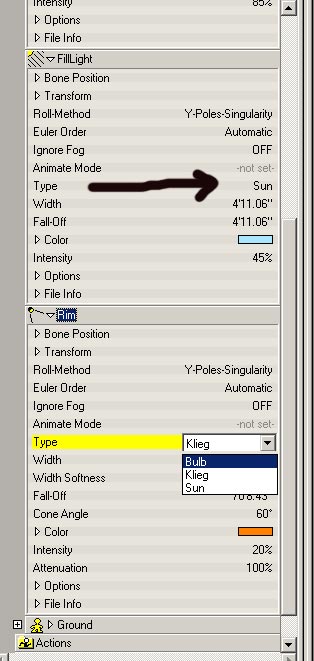
Klieg type is still in use today with A:M. If you look under the objects folder and inspect the rim light, or fill, or key light - you will see the property type - if you pull that down - you'll see that you could change any of the lights (key, fill, rim) to any type you would like - sun, bulb, or klieg. The terms key, fill, rim are just "standard" photography terms/names for lighting setups - You could rename them to george, harry, alfredo if you wanted.
-
No, I meant a Rim light. Other lights I would use if I wanted it to light up the entire surrounding. But for a light with a shade, I use Rim light that way I can control which way the beam is directed and its fall-off properties. I also use the Rim as a spot light. A Klieg would be good for a candle, I think, where the light eminates in all directions? Am I right? I don't know. The default rim light that comes in the default chor is a Klieg type light - a spot light. So I think we're talking about the same thing. The other types of lights are sun (one direction, parallel rays) and bulb (all directions).
-
What Dhar said - except I believe he probably meant to say use a Klieg type light. However you will also probably want to give your light bulb model surface properties some ambiance, and glow maybe to show that it is on - you will have to play with the settings.
-
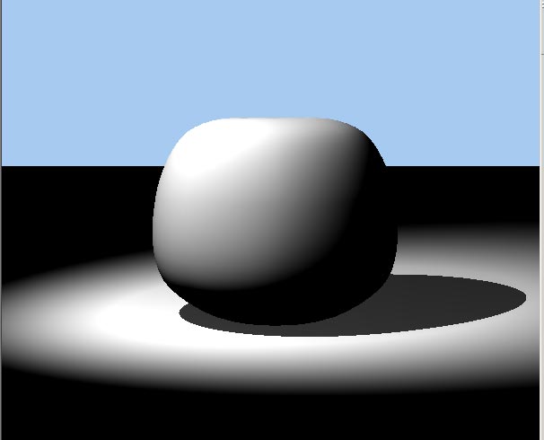
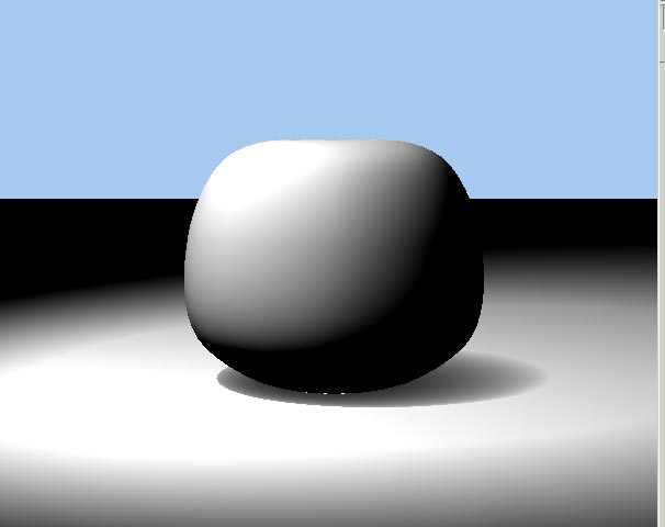
If you are using a Klieg light (and probably sun light) - you can increase the width of the light and it will sorta soften the raytraced shadows - I believe EDIT: first image is 1 inch width for klieg light, 2nd is 10 foot width
-
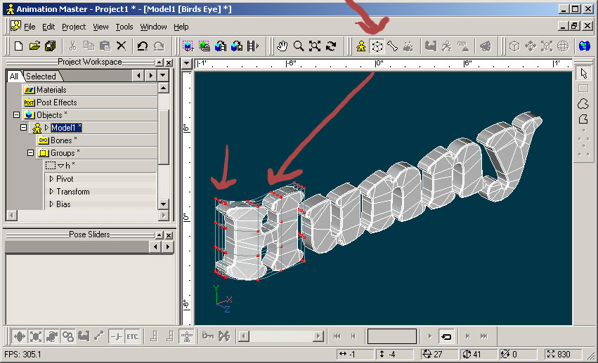
I am not sure I am understanding what you want to do: If you want to re-center the pivot of the group then select the group and hit "." twice. Then select the translate manipulator ("n") - the pivot should then be centered. You can then use the arrow keys (as well as your mouse) to translate the group. If you want to change where the pivot is for the group - ie make it NOT centered then you can also drag the pivot without dragging the group, or you can type in the coordinates for the pivot in the manipulator properties box. I found I had more luck first centering the pivot (with the double .) and then dragging the pivot, or typing in the coordinates. (ver 14c)
-
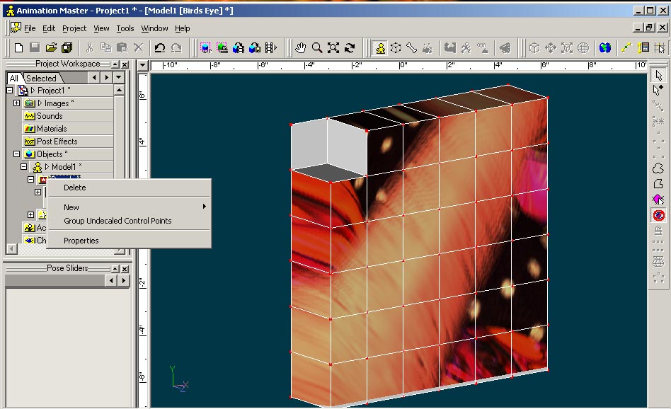
Perhaps at one point you extruded the 30 patched cover - and you have a double layer (ie 60 patches) for the cover. Perhaps you are seeing the second layer showing thru. Even so - whenever you have patches that don't seem to have the decal applied - you can always right click on DECALS in the PWS for the model and select "group undecaled control points" - you will then isolate the patches that still need to be stamped - and then can reapply the decal just to those patches. FYI, the face normals don't matter for decaling (for other things it definitely does matter) - you would still see the decal if it were applied, even if the face normals were wrong.
-
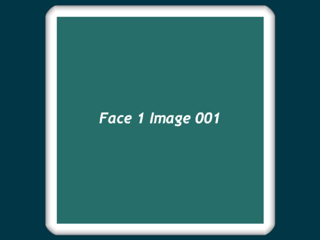
Ok - the cube came in without the decal for me too - but the decal container was there. It might be a problem with png format. I never use it. I changed the image to a jpg (in photoshop). tga should work too I then deleted the decal container - reapplied the decal (using the jpg) - saved the cube. Started a new project, brought the cube in - and the decal was there. EDIT: - I also changed the name to F1001-small.jpg rather than F1.001-small.png in case A:M was having problems with the name of the image - but I was just covering my bases without direct knowledge that this is a problem.
-
Are you also setting the frame number? (in the image decal container). You might also need to initially set the frame number of the sequence to 0. And check the fps for the image sequence & that it gets set correctly (under images). I notice that sometimes that doesn't stick as well. If you are going to be animating the display of the sequence of images - then you will also need to either set up a pose slider to control the frame number, or change it directly in the chor.
-
I will add - try to not center your focus of interest (offset it from center) - perhaps add some other elements for balance, and to lead the eye for a more asymmetric composition.
-
Any particular bone? and what rig are you using? The bone might have constraints on it.
-
Wow. Pretty terrific. Take a lesson from the consumable ink jet market. Make the software almost free - and sell the special magic-one-time-use green face dots for $20 bucks a dot. Kidding !!! (I need a video camera)
-

Happy (Early) Halloween
NancyGormezano replied to frosteternal's topic in Work In Progress / Sweatbox
Fabulous Jesse ! - Very funny - great visual impact, style - terrific camera work You should be proud. -
Try with desired gamma = 1 in tools/options/rendering (but it says my current gamma is 2.2 - that I set using adobe gamma) and make sure gamma =none, 1 in render to file settings That's what I have and I don't seem to see any difference in how it looks in A:M and what I render.
-
Whadda ya mean just around the corner? I thought it was always Halloween in your brain. Fun stuff as usual John. Heres an old 2D one I did preA:M (1998? 99?) when I wasn't as sophisticated, refined, and elegant as I am today: Yes it's true. A:M saved me from a bag ladies life of wandering the streets looking for my next Starbucks handout. http://www.intercad-inc.com/nancy/FishyTale/FishyTale.htm
-
Wow is right - beautiful! Have you tried: http://www.cgtextures.com/
-
Stunning! (I can hear the narrator now: "It was a dark & stormy night...")
-
make your own grid with the plugin grid wizrd with any number of squares you'd like Plugins/Wizards/Grid
-
You are looking for the distortion box icon (right next to the model mode icon). You will probably want to distort each letter separately. So make a group for each letter. Lock the letter. And hit the distortion box icon - then manipulate the distortion box splines so that the letter fits the curvature of the jar
-
You are right that you can't do constraints in modeling mode. But you could assign the cp's of each letter to a different bone (in bones mode) and move the bones (using the translate & rotate manipulators) to where you want the letters to intersect the jar. You could also just move the cp's of the letters in modeling mode (no bones) to intersect the jar. There are many different ways to do it (as the other examples showed as well). Just depends on what you want to do with this. If you want to animate the letters - then use bones. If you really wanted to use constraints for the model - you would create a pose/relationship & do the constraints (translate, orient) in the pose. The pose could be turned on and off - But my guess is that you don't want to animate the letters to be stuck & unstuck to the jar.
-
Have you thought of using a grid and then deforming the grid to your shape? essentially that's what I did when creating these 2d characters for illustrating someone else's story. I used the 2001 rig for animating http://www.intercad-inc.com/nancy/ProjectR...eKoolKeeper.htm You could apply a cookie cut decal to the grid to obtain irregular edges. You did say you wanted it flat - unless you don't really mean that.
-
That's called a cookie-cut decal applied to a patch.
-
fabulous powerful effective images, with wonderful design and balance. I have always loved so-called "primitive art" done by traditional peoples (as well as Picasso, Miro, Calder, etc). The distililation of form is immediately accesible and emotionally appealing. Complex imagery, patterns requires thinking on the part of the observer (which also has appeal) - but clean simple symbolic stuff is grokked immediately, and is universal. very very nice (makes me miss my roots as well, as I have always painted in a primitive art flat style)