robcat2075
-
Posts
28,261 -
Joined
-
Last visited
-
Days Won
404
Content Type
Profiles
Forums
Events
Everything posted by robcat2075
-
I like that Myron! That Alien needs cut down on the smokes!
-
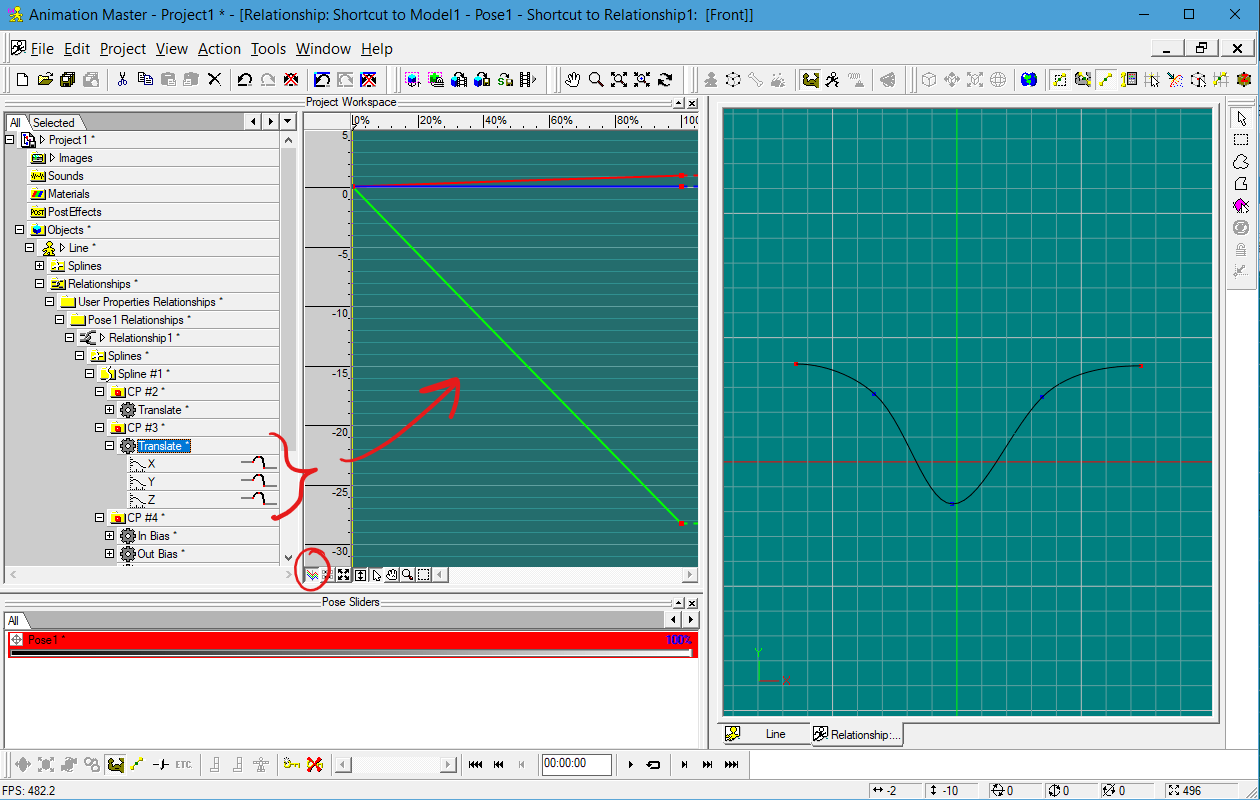
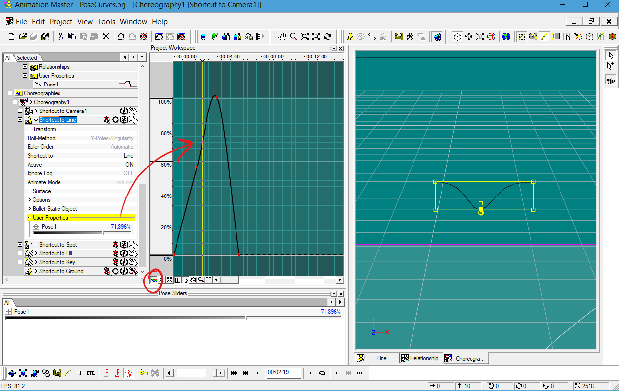
If the CPS were moved in a Pose, you'll need to edit the Pose to see the curves for the CPs. The key frames you make with the Pose slider in the Chor timeline will just store percentage values for that slider.

-
I've thought of one more mistake I made... At 4:51 we see the SHIFT options panel for Bake Surface. I should have set "margins" to 0 so that the tile for each patch wasn't padded with an extra pixel. One pixel wasn't highly noticeable, but zero would have been correct.
-
Converting a 2D material to a decal for cylinder wrapping...
-
 Of course, of course!
 -
Does double-clicking on its title bar not fix it? Try opening the Pose or PWS window, then re-docking Properties above or below that. This presumes either of those windows is still docked If that doesn't work, the total Help>Reset Settings will do it.
-
Steffen has pounced on that bug and lists it as "Resolved"... in v19.5 There is no timeline for a release of v19.5, it is still in alpha, so for now the work-around will need to work. I tested back to v15, the problem seems to be new in v19. Thanks for spotting that problem!
-
No soft shadows through translucent materials?
robcat2075 replied to R Reynolds's topic in Animation:Master
Yup, I think that is a render error. Can you post the test case? -
Thanks for the sample PRJ. I have submitted that as a bug https://reports.hash.com/view.php?id=7128
-
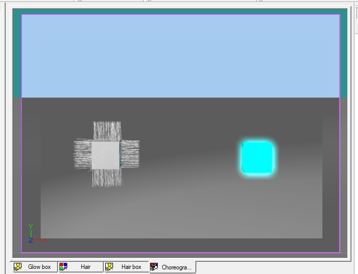
hmmm. With Multipass ON the hair doesn't glow With Multipass OFF the hair does glow
-
Could you post a sample case of objects that this happens with?
-
Does the character glow if the staff has not been added?
-
What happens if you add it in the Chor instead of as an action object?
-
Hmmm. Is that all one model?
-
Never mind! I've found an official Adobe player that can put up the video with a timeline slider.
-
Does anyone know a way to convert this example SWF to a conventional MP4 video file? There are several Hash Tech Talks in SWF format, which can no longer be played in browsers now that Flash is gone. I've tried several converter sites but they all fail in some way. One site I found will intelligibly play the SWF video but doesn't enable any scrubbing of a timeline. We need some way to convert these to regular video.
-
The Hash Tech Talk for Dynamic Constraints (and many others) can be downloaded from... The ones that are MOV format can be played in VLC media player Some of the presentations are in the old SWF format. Playing details on Tech Talk page.
-
Changing to from BIOS/MBR to UEFI/GPT "breaks" registration? Maybe?
robcat2075 replied to WolfsongCG's topic in Open Forum
Maybe we should ask @Jason Simonds what the standard login and password are to download off the Hash ftp site? -
You can do this constraint in the Chor but for a use like an antenna on a character you probably want to have it ready every time you use the character so doing it in a Pose is better.
-
No soft shadows through translucent materials?
robcat2075 replied to R Reynolds's topic in Animation:Master
Is that a z-buffered or a ray-traced light? -
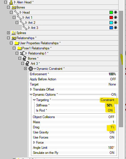
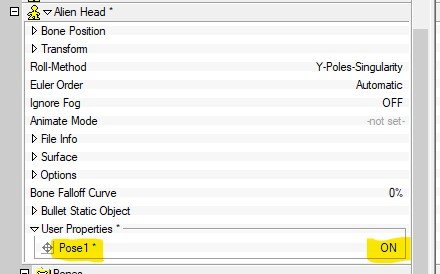
Here is a simple case you can try download this PRJ... Dynamic Demo001.prj In the Chor a simple alien head is animated to wag back and forth. on Objects>Alien Head... >New>Pose>On-Off In the Pose window the antenna has three bones. One the last one >New Constraint>Dynamic Constraint In the properties for that new constraint make the following settings... In the properties for the model turn the Pose ON... Play the Chor. The antenna should bend and wave. Experiment with lower "Stiffness" settings Experiment with higher "Drag" settings
-
BTW, when you asked about "Spring bone" I guessed you meant the constraint that is actually called "spring" If you mean dynamic constraints that work kind of like that antenna in "Alien Song" those do work properly in A:M. Is that what you meant or did you mean actual "spring"
-
I'm pretty sure Victor Navonne animated that manually. It's possible we had dynamic constraints in A:M back then but I don't think he used them for that project.
-
I think what happens is that if a patch is so small that no "patch" shows between the spline lines it doesn't get stamped. But if you zoom in, only patches that are visible in the window get stamped. So... I turned my monitor 90° so i could get the biggest possible vertical window to fit your model. I did Recall view/position to get your original alignment. I zoomed into see just the upper left quadrant and did an Apply Then I panned around to get the other three quadrants. That's why there are four stamps. You can on a stamp and choose "edit" to see the patches it covers.
-
She got the "bad" acid at Woodstock!