Search the Community
Showing results for 'snap to surface'.
-
A review of the Surface Pro 3 I didn't even know there was a 3 yet.
-
Snap group pivot to grid video tutorial Enjoy Snap_Pivot_to_grid_video_tutorial.mov
-
Over in the 'Buying a Cafe' topic Steve was kind enough to share his settings for Sub Surface Scattering. I know there are several topics on settings but this is something I've longed to understand versus just occasionally reference. His settings were: SSS with diffuse color of 253, 227, 185 SSS half distances 3,2,1 SSS extend group to avoid SSS borders General if not naive assumption: The SSS diffuse color settings operate as R,B,G settings in that the first number represents how much Red, the second how much Blue and the third how much Green. True/False? No where close to reality? If true then I would assume Steve's settings have a majority of Red (253) mixed with a good dose of Blue (227) with a mid level Green (185) applied to create his character's skin. I'll note that it's reportedly a good practice never to use extreme values/full colors (0 or 255) when setting RBG values and further assume the same will be a good practice with SSS. Added: Unless I'm mistaken these values equate to roughly 99% Red 89% Blue and 73% Green. Thoughts? Favorite Links? Recipes? One of my favorite links of old was Matt Bradbury's exploration of SSS here. That was at the very early era of SSS in A:M so some things might have changed. From that exploration it seems a key concept for SSS is to let the diffuse color of the Group feed into the SSS half distance settings to achieve the desired color/effect. This is what Steve appears to be doing via his settings. For those new to the topic of Sub Surface Scattering please visit the forum dedicated to that subject: Sub Surface Scattering Forum
-
I am having problems getting the Surface constraint working. I think I have done it by the book, but the bone that is supposed to move in line with the aiming bone does not move at all. I have set the aiming bone to aim at a target but when moving the target, the aiming bone follows allright but the bone is not following. (If I test by changing the enforcement on the Surface constraint it moves. But when moving the target it does not). If I make the bone a Child of the aiming bone it moves but it "hops around" sometimes and does not follow the surface smoothly all the time. (But the bone should not have to be a Child to follow the aiming bone, should it?) I have tested all the propertys I could find with no result. I had help on this forum before but those advices does not help me now. I have spent a week trying to figure it out. This should be straight forward but it is driving me crazy . Could anybody explain what I am doing wrong?
-
Using A:M's 'Snap to Grid' in conjunction with "Snap to Surface" will get this done and with a high degree of precision. Grids used with 'Snap to Grid' can be anywhere between .001cm and 10000cm if I am remembering correctly. Changing grid sizes on the fly while modeling is a great way to control precision placement of CPs. In this way, we can get two surfaces really close together without touching one another. Using A:M's 'Snap to Grid' in conjunction with "Snap to Surface" or any of a host of other modeling features will get this done and with a high degree of precision. Grids used with 'Snap to Grid' can be anywhere between .001cm and 10000cm if I am remembering correctly. Changing grid sizes on the fly while modeling is a great way to control precision placement of CPs. In this way, we can get two surfaces really close together without touching one another. Added: Grabbing a group of CPs and moving them doesn't conform to snap-to-grid and I'm not sure if this is by design or error. It seems to me that when 'Snap to Grid' is enabled everything should snap to the grid. There appears to be some tolerance issues in snapping to grid but I need to investigate. Moving with arrow keys always seems to snap the groups CPs to grid while moving with the mouse does not. Edit: It's primary scaling that breaks free of snap to grid. Perhaps the reason is that scaling and snapping to a grid would work against each other?
-
Ok, System Specs: Animation Master 14c (Win XP) Latest "Mirror Bones" Plugin for 14c Latest 2008 Rig ------------------ I like the 2008 Rig a lot (I think its the cat's meow really) but, after following the instructions, I am having trouble getting one function of the rig to work properly once I rig a character and I need a bit of help. Specifically, I'm having trouble getting IK legs area to work correctly with the 2008 Rig. When I move the IK Foot control away from or the leg, the foot always "snaps" away from the IK Foot control once the control is just beyond contact. It also "snaps" to the IK Foot control when I bring the control close enough to contact it. It is similar to looking at a magnet jump to another magnet that is brought close to it. I know that this is not how it is supposed to work. I compared my setup with the pre-rigged "Robby" model file that came with the rig and the Robby IK feet don't snap. I dissected the rig to see if my bones and targets were off after the install when compared to Robby's but they were not as far as I could tell. I even tried to install the setup for the IK Legs from scratch (without using installer process) using the bone setup and the corresponding relationships from the 2008 rig but, surprisingly, I had the same results. Does anyone here know what the problem may be based on the symptoms that I described? Thanks.
-
If I import an STL file I am getting a lot of surface artifacts where the surface is not smooth, and I have tried adjusting the peak angle. When I export I have no issues. Anyone have any ideas?
-
When using the rotate tool, it rotates in steps of 5°, is the a key that can override this rotate snap angle? For I'm quite happy with the rotate snap and all, but there are situation I don't want it and I find it a bit to much trouble going in to the settings tab to turn it off.
-
So I managed to settle on a project for the sci-fi contest, and if I finish it early I may do another entry. It seemed like a relatively straight-forward bit of modeling, but something isn't working quite right. It could be that I haven't sat down in front of AM for so long that I'm missing something obvious. Here is my problem: I've got one rectangular surface with another rectangle inside, and I'm trying to push the inner rectangle inwards to create a depression or indent in this robot (I would post an image but it will be immediately obvious what my project is, I think). I thought I knew what the problem was, I didn't have any splines connecting the 2 areas, so I put 2 splines per side and then pushed the inner panel inwards. While it looks right in wireframe mode it doesn't look right in shaded mode, there does not appear to be any indent at all. What do you figure I did wrong?
-
OK i have been trying to add some roundness to my creations with circles and ovals and such . and to that point i have been using the lathe tool to create wheels that are well ...... round. but i have encountered a problem. it seams that the lathe tool works on a 8 point system while the grid is only 4 . when i try to use the snap to grid option the points at 0 90 180 270 snap into correct position but the points at 45 135 225 315 snap to what ever point is closest. is there a way i can collect the cps as a full group and select only one of them to snap into the grid to aline the circle???
-
Hey Everyone. I'm in V18 and trying to get the SSS on a character to render without it looking black/ dark. It looks similar to when you try to render transparency with real AO and the "transparent AO" set to "Off" Anyone know how to get the SSS on without looking like black wax?
-
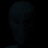
I'm having issues in v19o with rendering normal maps on non-rectilinear patches using anything thing other than a final camera render in a chor. At the top of the attached image are shown five flat surfaces. The left-most four patcher is similar to the surface that I was modelling when I discovered this. The next three surfaces have the same outline but each is built with a different patch layout to see its effect. The right-most surface is a reference square 4x4 patch plane. All patch normals are aligned. The same normal map image is decaled to each plane. Isometric views of these five surfaces are rendered as 5 pass progressive or 16 pass final in a modelling window, in a chor window (not thru the camera) and with the chor camera view. In all cases, the decal renders properly only on the 4x4 square surface or when it's a final render thru the camera. Naturally since everything renders properly in a final render it's not a show-stopper but it would be nice if a normal map decal always rendered properly. I've attached the project used to generate the illustrative images. nrml_map_test_embed.prj
-
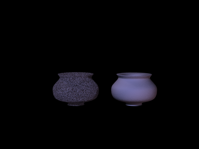
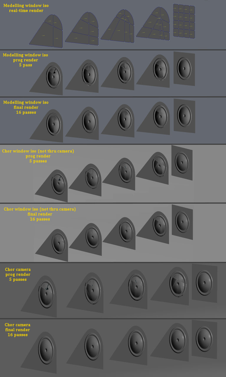
This is something I've been playing with I thought people might find interesting... Here's a render of two models. It's the same mesh copied from one file and placed in another. The surprise part is that they both have the exact same surface properties! The difference is that the first model is significantly smaller than the second one. It's scale has been changed in the choreography to match the second model. But notice that the roughness settings have been scaled to match. I've found I can get some interesting looks this way. Obviously, you could also experiment with the roughness amount and scale to get the look, but it's interesting to me that the effect scales.
-
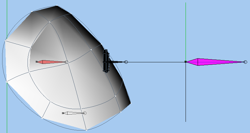
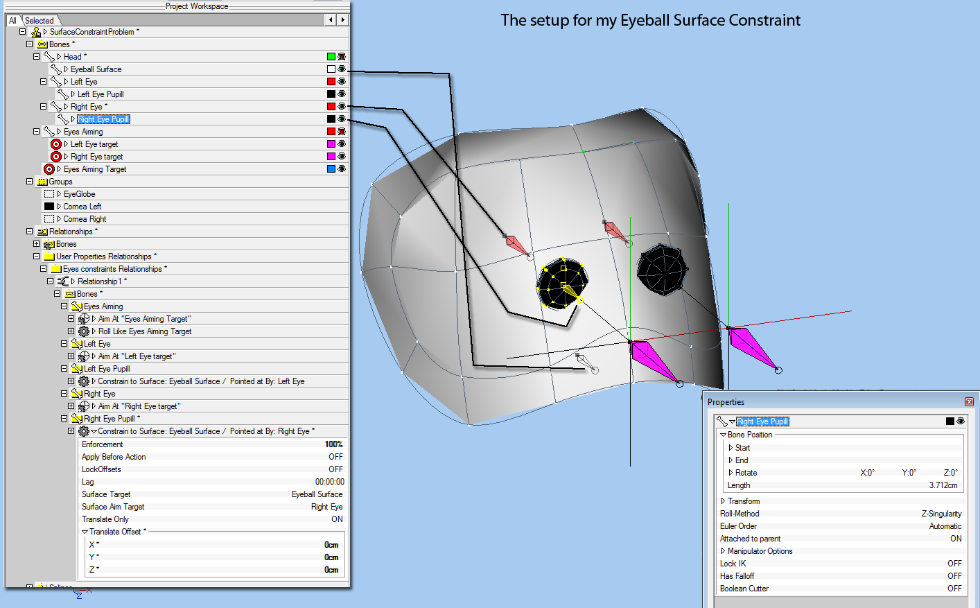
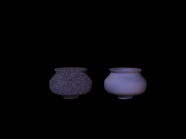
I am trying to use the Surface constraint to make pupils move on an irregular eye. I have got everything working exept for one detail: I can´t make the pupils align in the direction of the surface normals. As I understand it, the Property Translate only is the one controlling this. I have set it to ON but it still does´t behave as I want. I have tried to change all of the properties I could find, both for the constraints and for the bones I use. I also made sure that the normals were pointing outwards. I have run out of ideas... what am I missing here? This is the current alignment of the bone that controls the pupil mesh. Note that it is pointing in the same direction as the aiming bone. This is the desired alignment of the bone that controls the pupil mesh. Note that it is pointing in the same direction as the surface mesh normals. This is my setup for the surface constraint.


-
For a Star Trek parody, I am using AM to construct a CGI Enterprise Bridge set. I have successfully constructed the physical bridge, but am now trying to apply decals for the wall and console images. I was successful for the first two images I tried (planets picture, and Enterprise Diagram), then ran into distortion within the decal when I tried to apply the third one (Indicator Light and Plaque) to the Elevator Alcove Right Wall. Everything worked, right through the positioning process, but when I clicked on "apply," everything inside the decal distorted by expanding horizontally on the left and progressively contracting horizontally to the right, and stayed that way! This gave the look of everything being stretched out on the left to middle, and being squished over to the right. Things I have checked out: Working in Model mode and keeping careful track of my object group names in the hierarchy, I was very careful in all instances to be sure that I had selected only the surface upon which to deposit the decal, and to be sure that everything else was hidden. I worked in a Left view, with no perspective, and in Shader & Wireframe. What I ruled out was: 1. It isn't the decal image itself. I was rescaling the decal while positioning it, but this was done simply by moving the manipulator CP's, which visibly changes the scale uniformly, not in the severely non-uniform way the decal ends up when I hit "apply." I did the same procedure successfully decaling the Enterprise Diagram image on another surface with no problems. So I tried decaling the Enterprise Diagram on the Alcove Right Wall. But I got the same distortion I got with the Indicator Light and Plaque image. This ruled out the decal image as the source of the problem. 2. I thought that maybe the viewpoint was somehow responsible. So I tried being specially careful to orient the bIrd's eye view of the surface so that the viewpoint was normal to the surface. This did not improve anything. 3. I tried changing the viewpoint so that it was normal to the surface of the manipulator, rather than to the object (group) surface. This didn't help, either. 4. Finally, I tried rotating the entire model so that the surface to be decaled was parallel with the grid lines. This put the surface of the manipulator and the object's surface parallel to each other. Using a viewpoint normal to both the manipulator and the surface. I tried again. Still no improvement! The surface to which I am trying to apply the decal is a very simple, 4-point patch surface making up a vertical wall panel. There are no wrinkles or distortions in the patch surface, and it shows as a straight line when viewed from the top. I cannot think of any other geometric reason why this distortion should be occurring right at the moment of application. When I click on "apply," the undistorted, semi-transparent image I was using to position the image is added to by the transparent distorted image. Then, when I click outside the decal manipulator box, the undistorted image disappears, leaving a fully opaque and bright distorted image applied to the object surface. Argh! Has anyone else ever had this problem? If so, PLEASE let me know how you solved it! I'm trying to meet a deadline, and am really behind schedule! Cordially, Olvier Dean
-
Hi there, the new Retopo is very cool, and it really bridges the gap to the polygon world! What i miss is a "snap to vertex" enhancement for the retopo. Most polygon models have already a topological structure, which is by itself already a good guide for a retopo in A:M. Having a "snap to vertex" would help very much with models which are not ultra polygon heavy. For example, the head John Bigboote is using in his tutorial here http://www.hash.com/forums/index.php?showtopic=40992 would be remodeled in no time with a "snap to Vertex". I am no programmer, but i guess the "snap to surface" was much more complicated to make than a "snap to Vertex". Most likeley most of the logic and math needed is already in the "snap to surface". It would serve well in models with a average poly count, and the realy polycount heavy models like they come from ZB or 3D Coat can be treated best with with the "Snap to surface". Just for explanation why i got that "Snap to Vertex" into my mind: I just had to turn a polygon model in a NURBS model using Rhino. Snap to vertex was the most important fuction. And boy, while working on that, how often did i whish to use A:Ms Splines modelling with a StV function! Best regards Heiner
-
Has anyone worked out how to access the numeric keypad keys on a Surface Pro 2? I can get the on screen keyboard to display but the 'number pad' is simply the number keys and not the numeric keypad keys..... Cheers David
-
A ground up re-write just for ARM?... I doubt that can happen. Some years ago former A:M programmer Ken Baer told me that A:M has been rewritten from the "ground up" twice in its history. Both times it took six programmers about two years to get it to being stable and usable again. However, compilers are more powerful now than they were back then... Windows 11 on ARM gets big boost with rollout of ARM64EC It's not clear how much work the programmer has to do to to "recompile" for ARM, but maybe this sort of half-emulated/half-native is what could be done. Steffen is the expert, not me. I don't know if A:M runs on Windows on ARM or not. The Microsoft Surface Pro X is an ARM PC. I can't imagine them selling a PC that locks out all existing windows apps but then... a lot of their customers just run MS office apps and those have been made availabe in ARM versions.
-
A video and sample PRJ for making a surface constraint can be found this thread: Post#4
-
I assume AM will run on a Surface Pro 2 - has anyone tried this yet? Cheers
-

v19, v18, v17 New features and enhancements
robcat2075 replied to robcat2075's topic in * Latest Info *
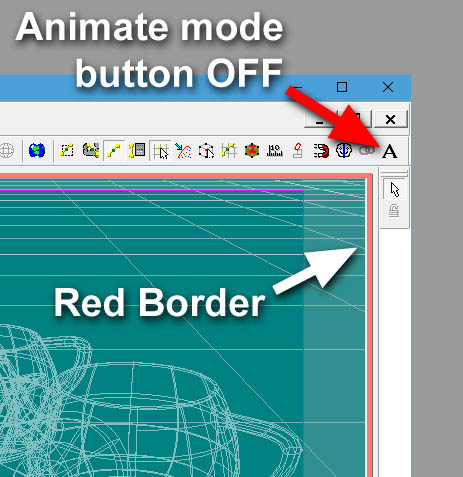
v17 New features and enhancements This page is not fully edited yet. Speedup Coding optimizations make rendering about 15% faster than in v16. Interface Animate Mode OFF warning v17 Red border appears around Viewport when Animate Mode is OFF. Animate Mode is sometimes turned OFF to make global adjustments to animation without making new keyframes. However, new animation can not be made with it OFF. D'oh! The new border warns the animator that "A" is OFF. It is possible to reverse the behavior of this border, so that the border is visible when the A button is ON by checking "Animate Mode warning reversed" in Tools--> Options --> Global. new Default chor v17 "Spot" light now white instead of brown. "Ground" has more patches for more visible perspective lines in shaded/wireframe camera view "Ground" set to allow shadowing by single thickness patches Further discussion of changes made with archived version of original default Chor. Introduction dialog displayed v17b At startup (like Tip of the day), which is pointing to resources for beginners Libraries -> Models - Some Primitives added v17c Zoom Fit after Paste now configurable at Options->Units default ON v17f Modeling "Prevent CP Assignment" property v17e for bones now property for bones is named "Prevent assigning cp's", if it is set to "ON"no cp's can't be assigned to this bone Frequently when rigging a model it is useful to use bones in relationhips within a model but undesirable for the model's CPs to be directly assigned (accidentally) to those particular bones. For example: A subset of bones for an FK arm control will never need the model's mesh directly assigned to it. Sometimes, some of the mesh can accidentally be assigned to the bones and reassigning the mesh and CP weighting back to the intended bones can be time consuming. I am suggesting here that an additional option in the properties window for the selected bone be added called "Prevent CP Assignment" (implemented like the "Lock IK" option). This would prevent the bone from having CPs assigned to it. Rendering Ambient Occlusion change v17 Occlusion Sampling can be set up to 200% (Render to File Settings) when the value is more than 100% a different algorithm is used for calculating AO (the result is a bit darker than the original one), this will solve the problem described in bugreport [bug]6176[/bug] Rendering is a reflection of artifacts Radiosity change v17b "Calculate Radiosity" no longer needed when you are doing a final render with Radiosity ON Sub Surface Scattering (SSS) changes SSS can now be used in materials v17 SSS property "Extend group to avoid SSS-borders" added v17 Selecting this option will cause to extend the group with their neighbor patches for SSS computation only Has only affect on groups, not if it is changed in the surface attributes for the figure self. The default value is OFF . SSS is now computed only at the first pass v17 for multipass rendering (exception stereo rendering or active motion blur) for choreographies a new menu entry "Calculate needed memory for SSS" v17 This calculates and displays the memory, which will be needed for the SSS computation at rendertime and inform the user about this value or warn if too much memory will be needed for computation, it writes also additional information's about SSS to the logfile a case where SSS computation will need to much memory is as example, if You have very small values for "Half extinction distances" (Red 0.1,Green 4,Blue 5) in conjugation with a high sample area (compute from surface which is covered by SSS) will need around 12 GigaByte for the SSS computation the "Relative density of SSS samples" has also a influence here (the sample projectfile for the values above are from the report [bug]6174[/bug]) Particles/Simulations Baked sprite systems - breaking change v17b Baked sprite systems from v17b onward are not backward compatible, due a needed format change for baking more than one sprite emitter too. Older PRJs will need to be re-baked. Sprite emitters have additional properties v17b - "Single Particle" , default is OFF if this option is set to ON , only one particle is created , when it dies, a new particle will be created the following 3 options having only an effect with image sequences - "Randomize the image sequence" , default is OFF if this option is set to ON , each particle is displaying a random frame from the image sequence (and this means each time the frames are randomized , for a repeatable result bake this particle system) setting this to ON disabling also the next two options - "Image sequence start at particle birth" , default is OFF the old behavior for sprite emitters if this option is set to ON , the image sequence starts first when the sprite is created - "Repeat the image sequence" , default is OFF if this option is set to ON , the image sequence is repeated over the particle life Animatable parameters for SimCloth (not ClothWizard) v17c Fixed only for Simcloth. But be warned, changing simulation parameters (like stiffness) over the time , having a high potential to make the simulation unresolvable. For the Clothwizard (the old cloth scheme, superceded by SimCloth) We don't change the current behavior (simulation parameters are not and will be not animatable) Other New expression keyword "AtTime(time, n)", v17e where time is the time for which You want to have the value for n , n is the Bone information Example: AtTime(GetTime()+SetFrame(2),..|..|..|..|Model1.Transform.Translate.Y) where GetTime()+SetFrame(2) , evaluates the Y position for Model1 at the current chor time + 2 frames SetFrames() is also a new keyword, setting the time value in frames based on the current fps, time value is always based on seconds polygon export plugins now supporting 32 and 64 polygons/patch v17d STL files can now imported as prop or model v17a Amplitude Plugin v17e Create keyframes for a property in a chor or action, based on the amplitude from a wav file Amplitude Plugin Documentation Amplitude Plugin sub-forum has user examples and PRJs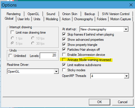
-
Version 17 works just fine but v18 displays nothing is any view - I tried Open GL and Open GL3 but nothing shows in any of the windows (model/chor etc). So what am I doing wrong? Cheers
-
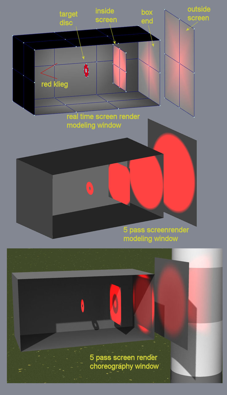
I'm building a railroad indicator lamp, essentially a red/green traffic light. I wanted to simulate the look of the optics of these lights which were designed by mounting an incandescent lamp at the focal length of a coloured glass fresnel lens (like in a lighthouse) such that its light is only visible when viewed almost on-axis as one would from a long distance. I think I've come up with a believable result using a hierarchical klieg light mounted inside the enclosure. It's aimed to shine inside the case and illuminate a small internal disc, standing-in for the lamp filament, sitting near the focal length of the lens. Viewing the indicator while it turns in front of you produces a result I'm satisfied with. semaphore_test.mp4 The problem is that, as far as I can tell, hierarchical lights (sun, bulb or klieg) do not handle well the shadows of other parts of the model. I set up a test model that's similar to my indicator lamp. Inside the open sided box is a klieg light aimed at a target disc that in this case has a hole in its centre. In any render from the modeling window there are no shadows generated by any surface regardless of whether the shadows are ray-traced or Z-buffered. Strangely a chor render does have translucent ray-traced shadows but the light still passes through the entire model and falls on an external model. My work around was to make an inside screen that was totally black so the light hitting the rear of the case is absorbed and only the target disc is illuminated. As for the light leaving the back of the enclosure, I'm fortunate that there will be about 4 ft. (1.2 m) between the rear of my indicator lamps and the nearest surface so I should be able to set a fall-off value that minimizes the spill. I suppose since hierarchical lights are typically used for things like automobile headlights this has never been an issue before. However you'd quickly notice this glitch if you were trying to shooting a night scene using the dome light of car as illumination. The passengers would have shadows while the other parts of the car would not. Obviously the ultimate work-around would be to add the lights in the chor but it would be nice to have this convenient feature work.
-
When I bake a surface is there a place to choose its resolution ??
-
I had an idea for a some alien creature that would not have any surface shading, but just an outline to it. Is there a way to use the toon lines to do that and make the surface completely transparent or not visible and just show the outline of the model?