

Oliver Dean
-
Posts
8 -
Joined
-
Last visited
Oliver Dean's Achievements
New User (2/10)
0
Reputation
-
For the sake of curiosity, and to help solve this mystery - perhaps you can upload a zip file that contains a model that just has the 2 vertical walls (good and bad) along with the image you are using for the decal. -hmmm... not quite understanding this statement - but perhaps this is a clue to problem? Thanks, HomeSlice, Nancy, and Frosteternal. I haven't gotten to the final render stage yet (have to review the manual to find out how to do this!), so I can't answer your question about it for a day or two. The problem shows in the View Render options of Shaded and Shaded/Wireframe. But!!! The HomeSlice method worked, and got me a workaround I can use!!! Y-a-a-y!! Actually, it is a different decal I wanted to use, but for the sake of clarity in our correspondence I used the same one for the "bad" surface as the one for the "Good" surface. When I copied the "good" patch surface, it copied without the decal. I simply resized it to a teeny bit larger than the "bad" surface, and applied the correct decal successfully without distortion. Then I positioned the copy over the "bad" surface a hair's breadth away, saving me the hassle of removing the old patch surface from between two adjoining patches. As for Nancy's questions: I have been using version 15.0f since yesterday, which I downloaded and installed from the ftp (I have the email subscription version). Apparently this may not be related to the problems you have been experiencing, because it occurs for me with both alpha channel decals and non-alpha channel decals, and it does not occur on the panels across from the "bad" one. For clarification: When I said that both patch surfaces originated from the same vertical extrusion, I simply meant that I extruded a segmented spline at floor level upwards to create all the walls of the elevator alcove at one time. These two patch surfaces originated from different segments of this single, extruded floor-level spline. You would think that two simple patches from this extrusion would behave the same, but N-o-o-o! At least, we now have a work-around! Nancy, my apologies, but I am fighting a fearsome deadline involving several tight milestones until August 21. What I'll do is save an appropriate version of the model with the bad and good surfaces, and if you are still interested after the 21st, I'll extract some samples to send to you. I already sent an email to Hash Support describing the problem, and if they come up with any answers, I'll let this thread know. Thanks again for all your help! I think we can say that we have a good work-around, although a corrective or preventive solution is always welcome and preferable. Cordially, Oliver Dean
-
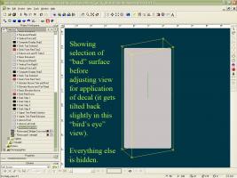
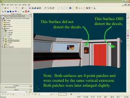
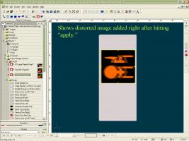
Thank you, Rob T, Pixelplucker, and John Bigboote. Regarding Rob's suggestion, as well as Pixelplucker's, I had already thought of that; as you see in the 3rd illustration, the viewpoint was carefully oriented so that it was square on to the patch surface -- I show the image just before the last tweak where I tilt the patch surface back a little in the view before applying the decal. In addition, I tried rotating the entire model so that the patch surface was parallel to a grid axis. Doing this made one of the standard views (in this case the Left view) normal to the patch surface. I also tried rotating the model so that the patch surface was square on (normal) to the Front view before applying the decal. None of these attempts worked. Rebooting the computer didn't help, either. Regarding John's comment, unless I misunderstand you, I think that is already the way I am doing it. The surface (target patch) is identified as a group, and when I select the group, this enables me to isolate the surface by hiding everything else. Then I reorient the viewpoint (if necessary) and try to position and plunk the decal in place. The group selection and isolation ("h" key) is what I did for all the illustrations after number 1. What I'm doing is very simple -- it just distorts on this patch surface. As you can see from the rendered images, the patch surface is perfectly flat with no wrinkles or other patch artifacts. It's as though there were some undocumented surface characteristic that is throwing off the decal's horizontal linearity when the "apply" button is hit. I can't find any difference between the patch surface that works and the one that distorts. They both were originally created from the same vertical extrusion. I'm really baffled! I am grateful for your inputs, but still no cigar! Cordially, Oliver Dean
-
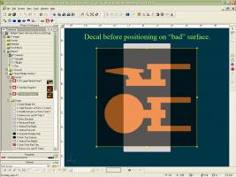
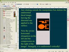
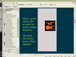
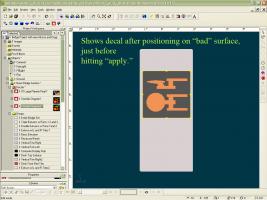
Thank you, Nancy and Robert! I'm still getting used to this forum format -- hopefully, I can get this reply to attach some clarifying screen shots. Nancy, I tried your recommendations (upgrading to Version 15.0f, and putting on a larger decal first, with the same color as the surface. Neither helped. I am attaching a series of pictures illustrating: 1. An overview of the model, showing the location of the two surfaces in question (one that did not distort the decals I applied, and the one that did). 2. The successful decal (no Alpha channel) on the "good" surface. 3. The selection and "bird's eye" view of the "bad" surface before final adjustment of its viewpoint for dccaling. 4. The same decal as in #2 above after being newly generated but before positioning on the bad surface 5. After positioning (just before hitting "apply") 6. Right after hitting "apply" 7 Right after clicking outside the decal area. This is a consistent, repeatable problem that always occurs with the "bad" surface, no matter what I do. I have tried at least a dozen times to get it to work, with no success. Ideas, anyone? Cordially, Oliver Dean Hope that this clarifies the problem, and triggers someone's memory of a similar experience I'm retranmitting the pictures - I think #7 was missing. For some reason, my 4th picture was inserted at the beginning of the stack. Please view them in numerical order. Thanks! -- O. Dean


-
Thank you, Nancy and Robert! I'm still getting used to this forum format -- hopefully, I can get this reply to attach some clarifying screen shots. Nancy, I tried your recommendations (upgrading to Version 15.0f, and putting on a larger decal first, with the same color as the surface. Neither helped. I am attaching a series of pictures illustrating: 1. An overview of the model, showing the location of the two surfaces in question (one that did not distort the decals I applied, and the one that did). 2. The successful decal (no Alpha channel) on the "good" surface. 3. The selection and "bird's eye" view of the "bad" surface before final adjustment of its viewpoint for dccaling. 4. The same decal as in #2 above after being newly generated but before positioning on the bad surface 5. After positioning (just before hitting "apply") 6. Right after hitting "apply" 7 Right after clicking outside the decal area. This is a consistent, repeatable problem that always occurs with the "bad" surface, no matter what I do. I have tried at least a dozen times to get it to work, with no success. Ideas, anyone? Cordially, Oliver Dean Hope that this clarifies the problem, and triggers someone's memory of a similar experience


-
-
For a Star Trek parody, I am using AM to construct a CGI Enterprise Bridge set. I have successfully constructed the physical bridge, but am now trying to apply decals for the wall and console images. I was successful for the first two images I tried (planets picture, and Enterprise Diagram), then ran into distortion within the decal when I tried to apply the third one (Indicator Light and Plaque) to the Elevator Alcove Right Wall. Everything worked, right through the positioning process, but when I clicked on "apply," everything inside the decal distorted by expanding horizontally on the left and progressively contracting horizontally to the right, and stayed that way! This gave the look of everything being stretched out on the left to middle, and being squished over to the right. Things I have checked out: Working in Model mode and keeping careful track of my object group names in the hierarchy, I was very careful in all instances to be sure that I had selected only the surface upon which to deposit the decal, and to be sure that everything else was hidden. I worked in a Left view, with no perspective, and in Shader & Wireframe. What I ruled out was: 1. It isn't the decal image itself. I was rescaling the decal while positioning it, but this was done simply by moving the manipulator CP's, which visibly changes the scale uniformly, not in the severely non-uniform way the decal ends up when I hit "apply." I did the same procedure successfully decaling the Enterprise Diagram image on another surface with no problems. So I tried decaling the Enterprise Diagram on the Alcove Right Wall. But I got the same distortion I got with the Indicator Light and Plaque image. This ruled out the decal image as the source of the problem. 2. I thought that maybe the viewpoint was somehow responsible. So I tried being specially careful to orient the bIrd's eye view of the surface so that the viewpoint was normal to the surface. This did not improve anything. 3. I tried changing the viewpoint so that it was normal to the surface of the manipulator, rather than to the object (group) surface. This didn't help, either. 4. Finally, I tried rotating the entire model so that the surface to be decaled was parallel with the grid lines. This put the surface of the manipulator and the object's surface parallel to each other. Using a viewpoint normal to both the manipulator and the surface. I tried again. Still no improvement! The surface to which I am trying to apply the decal is a very simple, 4-point patch surface making up a vertical wall panel. There are no wrinkles or distortions in the patch surface, and it shows as a straight line when viewed from the top. I cannot think of any other geometric reason why this distortion should be occurring right at the moment of application. When I click on "apply," the undistorted, semi-transparent image I was using to position the image is added to by the transparent distorted image. Then, when I click outside the decal manipulator box, the undistorted image disappears, leaving a fully opaque and bright distorted image applied to the object surface. Argh! Has anyone else ever had this problem? If so, PLEASE let me know how you solved it! I'm trying to meet a deadline, and am really behind schedule! Cordially, Olvier Dean
-
You can use a ambiance-intensity-map to make that possible. It is a greyscale-image where the full ambiance-areas are represented by white and the none-ambianced parts are black. Or you can create a group and manipulate its surfaceproperties. The group should have the exact same size like the decal. *Fuchur* Would the Ambience-intensity-map then be a solid white area the size of the decal in order for the entire decal to retain brilliance in shadow? Or does it have to have some sort of variation to match the image of the decal?
-
Hi, all! I'm creating a Star Trek Enterprise Bridge approximation that I can render in Stereo stills to substitute for green screen backgrounds I've got the basic bridge structure done OK, but I have to put in the computer screen images with decals. To make the decals look like they are illuminated computer screens, I need to set their ambience to 100% (or higher?0). But when I apply the decal, the Workspace on the left does not reveal any adjustments for ambience under the decal, the image, or the stamp. Any suggestions? Is there another way I can accomplish the illuminated screen look with a decal? Thanks in advance for any expertise you can offer!


