robcat2075
-
Posts
28,298 -
Joined
-
Last visited
-
Days Won
407
Content Type
Profiles
Forums
Events
Everything posted by robcat2075
-
Yes. This makes the decal not get shadowed by anything and not need any particular light on it, Yes and yes. If you use the image decal to drive ambiance, then white will be white, but a 50% gray driven by 50% ambiance will only render 25% gray. 50% gray with 100% ambience will be 50% gray, which is what you want.
-
The standard route for a TV screen is to put the image decal on the screen surface and set the screen to 100% ambiance. That works. You'd have to show me a case where that is not appropriate. If you can't remodel your screen to the dimensions of your image then a still frame decal for ambiance would be the way to make just the image part luminous.
-
Show more than decals? yeah , have you got Skype? I'm rholmen. Send a contact request.
-
On the OpenEXR.org website there's a PS plugin for EXR. It converts the image to 16 bits which is better than 8 but less than what EXR can do.
-
smart idea. I have the same image applied in the same spot twice but one is for ambiance and one is for color. It gives me the look I want but I think this may be adding to the problem. Is there another method? Do you really need the image to do ambiance? Couldn't you just set the surface to an ambiance %? Not that two decals shouldn't work as well as one.
-
A slight blur post effect might also help in anti-aliasing instead of oversampling? Reduction in resolution of the original render averages the pixels in some manner which is a form of anti-aliasing. Same with blur. It looks to me like displacement runs into problems when it resolves to less than 1 pixel. That's what anti-aliasing is for. Well, let's try that. Here's the same three panels, but the top {original] render at the top is blurred 2 pixels, which is a lot of blur. treads11Single_blurredMP4.mov The flicker is still there, blurrier, but still obvious. Downsizing a larger render is the only way to get more actual anti-aliasing. But I'm glad even that works. I thought it was hopeless.
-
BTW, EXR also has a "flat" color buffer. I think it's "diffuse" An occlusion pass looks like a classic "White render". Much as Nancy hash shown.
-
Here's a comparison of single, double and triple resolution renders of the problem spot. Flickers and ripples are gone in the triple res render. treads11SingleDoubleTripleMP4.mov I'm sure it's slower. Also, Displacement only shades properly in multipass so you can't take advantage of faster regular renders. I'm finding that over-rendering helps in A:M too.
-
I know it's been used successfully before. The decal has a property somewhere for frame currently shown. Try setting keyframes on that.
-
Would >save as animation work? CHoose targa as the new format. EXR is treated like an image sequence. Use the Composite controls to turn off all the other buffers and then resave what's left to a new targa sequence.
-
Here's a brief clip showing some of the oddness complex displacement patterns have when animated. treads11_LoHiComparison_H264.mov Watch the top version around the edges of the tread and you'll see strange flickering and rippling. I think it has something to do with displacement texture being seen at a very shallow angle. The ripples seem to be about one pixel in size rather than all different sizes, which makes me think that somewhere between the material that generates the grayscale pattern and the actual displacement process, a value is getting passed thru a lower precision than it ought to be. Just a guess, I really don't know much about how it all works. The bottom is the same frames, but rendered at double res then shrunk down. Less flickering and rippling, but not completely gone either. Its ripples were about one pixel on the original large frames also. Haven't tried quadruple size.
-
Possibly, although a propeller is so much simpler than tank treads to rig and animate that doing it conventionally is probably better. Yes, that would be very much like tank treads. I'm not sure we have a combiner that would make a nice cylinder shape for the bullet casing. Bullets move thru their positions so fast that strobing might be a problem. This tank tread thing is best for repeating shapes that move quite slowly.
-
Does that handle corner-turning?
-
There's another hard thing to teach. Rotating the materials (there's four that have to move exactly together) just the right amount so the tread appears in synch with the ground is tricky. It's not quite right in my demo. Yes. You'd animate separate instances of materials on each tread. About 10 years ago I went to a talk by one of TRON guys, Chris Wedge. He said there was no interface in their software at all. Everything was done by coding on punch cards to control the renderer. Ouch.
-
Thanks, everyone, for your positive comments! That's exactly right. It's all "Extended GridTurb" combiner. My problem is figuring out how to teach it beyond just giving an exact series of steps. As it is, the process is rather un-intuitive. The tree you make in the PWS gives little hint of what the result will be. If we could drag and copy nodes in materials around that would be a big help, but we can't. Also, these displacement things can behave very oddly in animation. How to explain that it's not going to be perfect?
-
Probably not, displacement is tedious to render. In this case 16 passes take 2.6 minutes per frame.
-
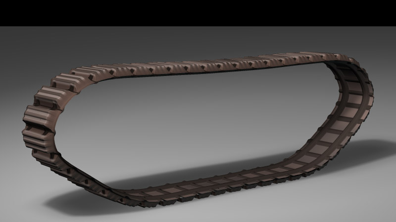
Here's a slightly more detailed treatment of the tread. (I have no idea what is on the inside of tank treads.) Another day lost to A:M! I started this just before lunch and got the basic tread concept working in an hour, but then i couldn't leave it alone. Now my stomach is grumbling. I think you're limited to one displacement material on a surface. But you can model the bulge in the tire and spin the tread on the model, much as I'm doing here.

-
What would be the least obvious way to make tank treads? Tank treads made with, what else... procedural materials! The top is the final render, the bottom is the wireframe. treads9CompH264900.mov
-
What you are asking doesn't quite make sense. I suspect there are several terms confused. However, If you're on A:M v15 the OBJ importer will be included already If you just need to render the obj into a flat image you can RightMouseClick on the Objects folder in the PWS>Import>Prop The imported OBJ can be put in a chor and lit any way you want and you can render the scene to a TGA. Imported OBJ often look washed out or too bright. You will need to set the "ambiance" for all the groups in the object to zero.
-
Those are looking good. I agree. In the absence of scarve or capes or hair, a fundamental thing to do would be to pose them like they are moving forward fast. Have them grabbing the hand rail and leaning forward or... being pulled back. Anything but straight up and down.
-
You can adjust the angle and magnitude of the spline thru any CP with bias adjustments. Turn on the "Show Bias" button to see the adjuster. You can turn it and pull it to suit any shape. Shift and CTRL modify how it works.
-
When you turn the ALPHA buffer ON, the background will appear black ( aka nothing) until you use the image in an app that reads the alpha channel and lets whatever you put behind your render show thru the black. If you use the image in A:M as a rotoscope A:M will read the alpha channel and make the black part transparent. But when you first render your image it will look black since there is nothing behind it in the render window.
-
If A:Ms current regular render DOF effect could be allowed to produce a greater blur it would probably be quite good, it's already being driven by the depth map A:M uses internally.
-
You can constrain any model to a bone in any other model in the Chor. You can also drop a model in an action to use with a character in that action "Conforming" clothing... no. It would have to be a mesh specially modeled with bones in the right place to constrain to bones in the character model. I imagine Poser clothing isn't just any old model, it's a model made to work with whatever their conforming process needs.
-
IF you just need one still, I'd say model the new shape. You modeled the others, why not? That will be faster than trying things you're not sure of.