


robcat2075
-
Posts
28,264 -
Joined
-
Last visited
-
Days Won
405
Content Type
Profiles
Forums
Events
Posts posted by robcat2075
-
-
Since the A:M forum doesn't handle financial transactions it probably isn't a prime hacking target, but it is easy to discontinue this weak security practice.
-
This change doesn't end hacking attempts but it does stop providing them with half of what they need for an easy one.
-
11 minutes ago, Roger said:
While I don't have a problem with this in theory, wouldn't someone already have to have your password in order to sign in? I'm not sure how switching to the email address makes it any more secure, unless you're going to set up an option for 2FA.
Here is the explanation from the makers of the forum software...

-
Hey @Jason Simonds,
I just tried logging in with my email address (it's already an option) and it doesn't work.

When that gets sorted out I recommend that some very visible alert to the change be added to the standard sign in screen. I think most people will not notice the mere absence of "Display Name" in this box.

-
Thom's kid needs a doggy downer.

-
-
Remember that annoying kid in "Temple of Doom"? He's an Oscar nominated actor now!
Quote
“Everything Everywhere” represents a major career comeback for [Ke Huy] Quan, who rose to fame as a child actor in films like “The Goonies” and “Indiana Jones and the Temple of Doom,” but quit acting for decades when he found roles for an Asian actor hard to come by. While watching “Crazy Rich Asians” in 2018, Quan began to mull a return, and two weeks after asking an agent friend to represent him, he was sent “Everything Everywhere” and went out on his first audition in years.Extended NYT article on 2023 Oscar Nominations

-
Some brief animation rendered with Radiosity. Still has a few flickers and odd bits...
-
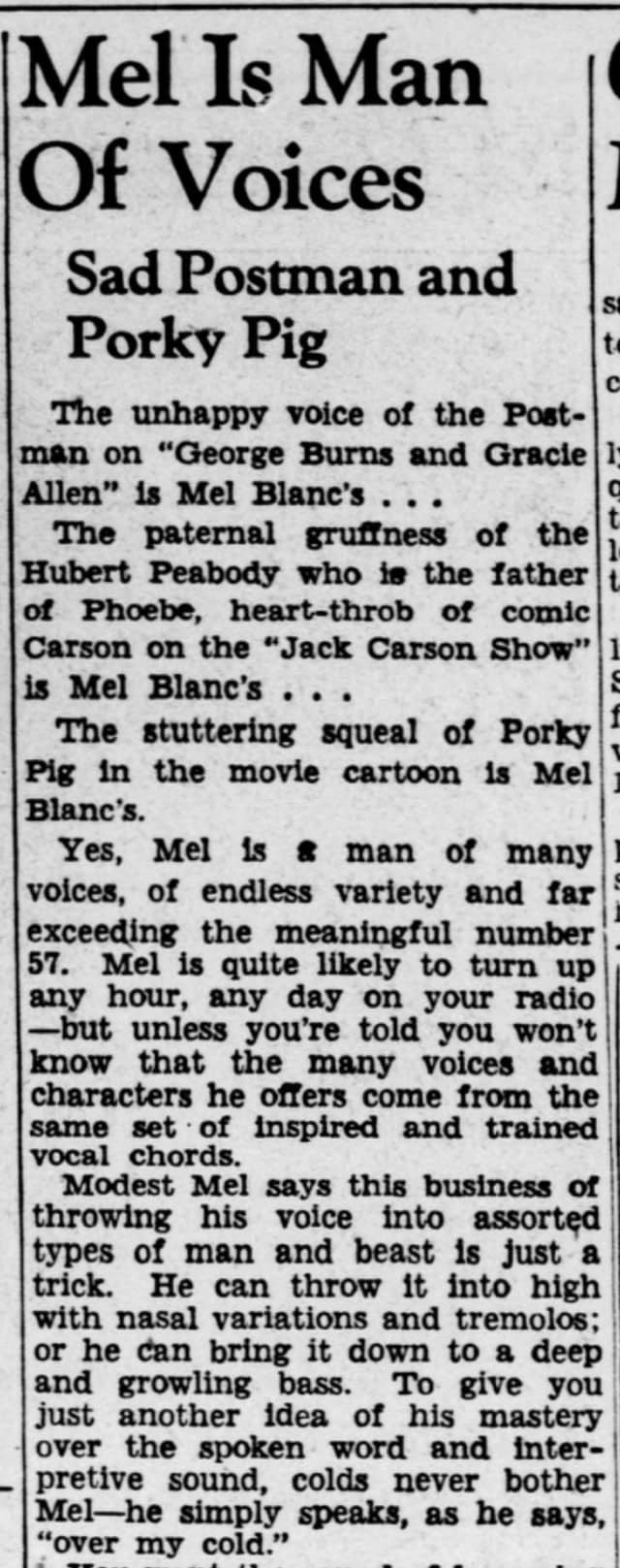
...from a Facebook post, a 1944 Pittsburgh Press newspaper clipping about Mel Blanc.
Played the violin? And tuba?
As with all reporting on the entertainment industry, one should regard various details as possibly true.

-
Great character and great model, @detbear!
You can upload models to the A:M Exchange where user model contributions can be found found.
Forum >The A:M Exchange - Resources Center > Free Models! Materials! Projects! > Models
https://forums.hash.com/forum/173-models/
I suggest the "Clothing and Accoutrements" subsection
If it has any external image maps I suggest putting it all in a standard zip.
Thanks! -
We are still open to people wanting to try C++.
We have potentially three eager-to-start-C++-ers so far.
The basic plan of the course is this...
- There is free Udemy course with videos (10-20 minutes) for each lesson and a small programming project associated with the new thing taught in that video
- You watch the video. Probably re-watch it.
- You code the program
- You bring your finished program to our meeting. If it runs, great! You can show us what you did that was creative or unusual. If it doesn't run. we look at it to figure out what went wrong and get you back on track for the next lesson.
-
I see
QuoteWorldwide Box Office $2,023,961,353

-
Here is an enlarged side-by-side of Photoshop NR, the original image and the AI NR. Of course they both have multiple settings that will vary the result.

-
I'm still seeing $1.9 Billion. Who is reporting $4.6?
-
I get ads on Facebook for AI noise reduction programs.
I tried one on A:M Radiosity renders which have noticeable noise (speckling). It's pretty good. Better than Photoshop noise reduction.
You'll need to click on them to see it at 100% to see the original noise clearly.


Notice the loss of reflection detail in the wheel...

-
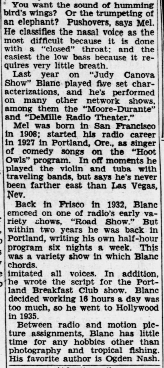
My spacepod. They always seem to land in inconvenient places
-
8 minutes ago, detbear said:
Hey RC......About how long are those renders taking?
Between 5 and 10 minutes. For quality good enough for animation the time would need to go up to reduce flickering.
-
I recall when radiosity renders took hours. Now it's a few minutes.
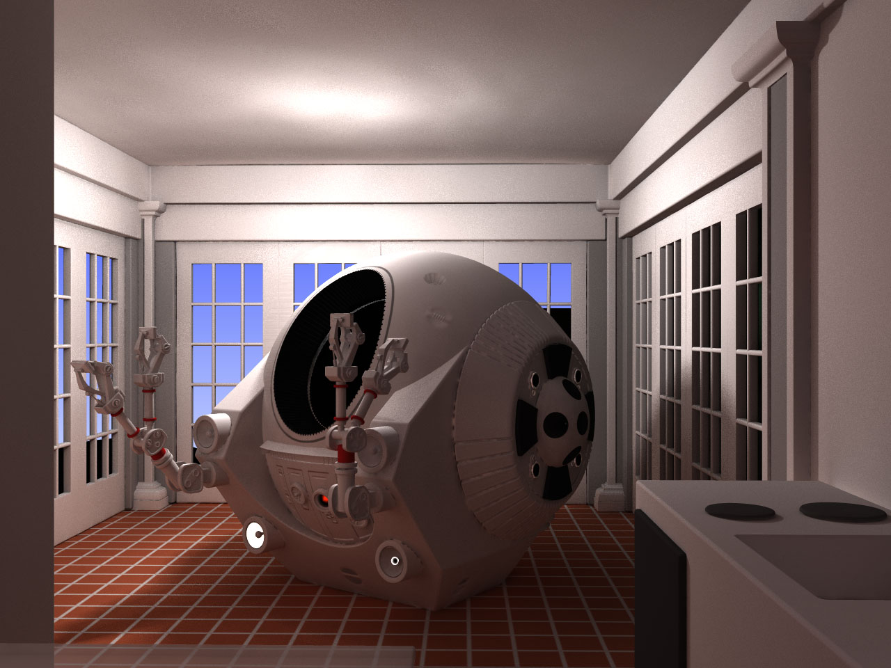
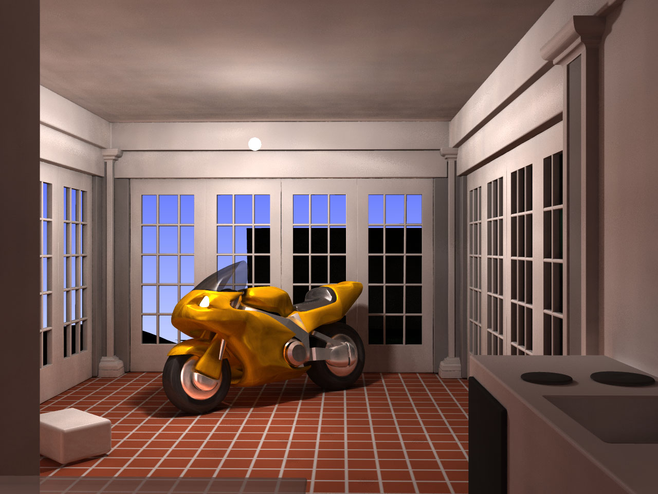
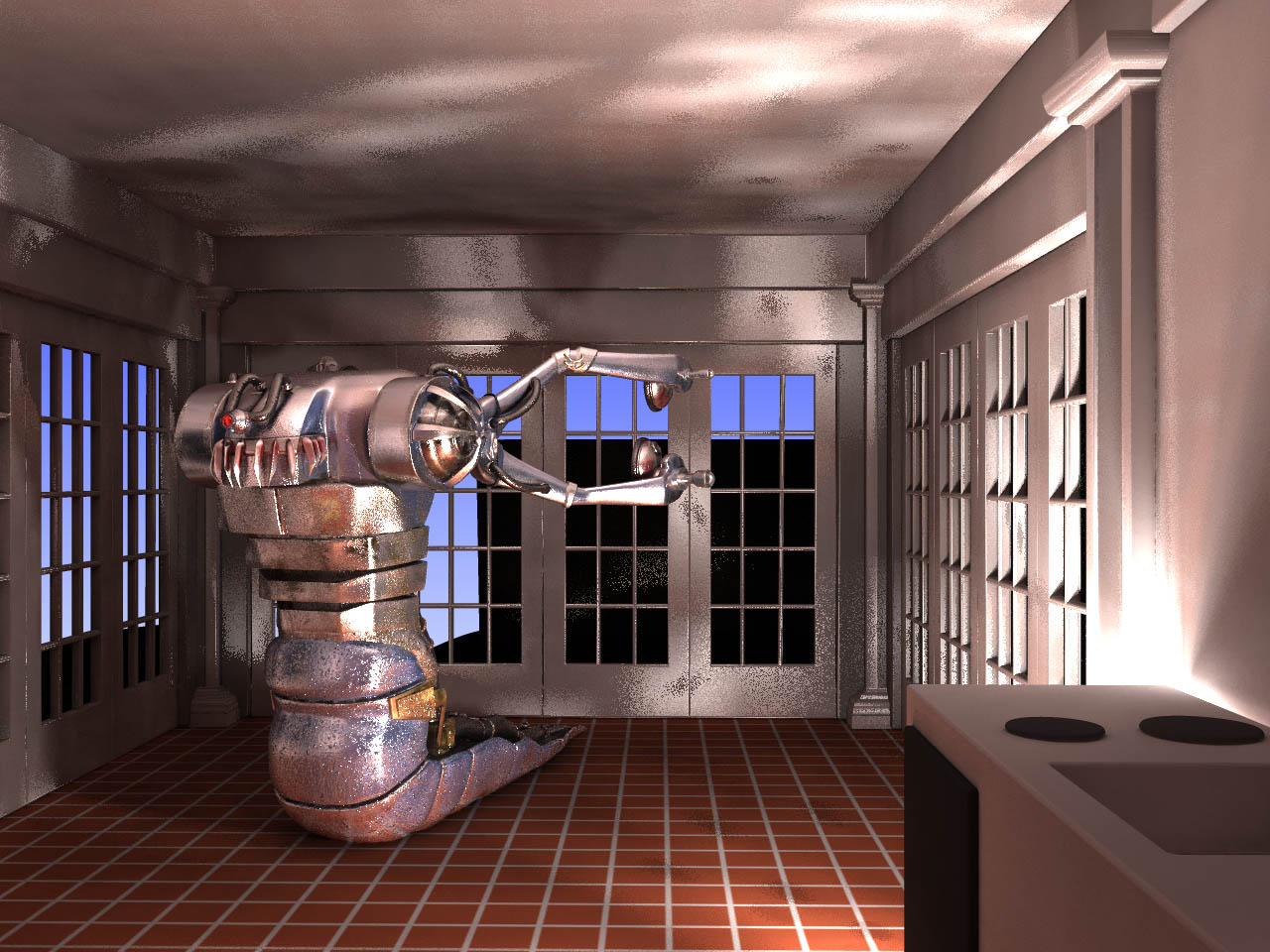
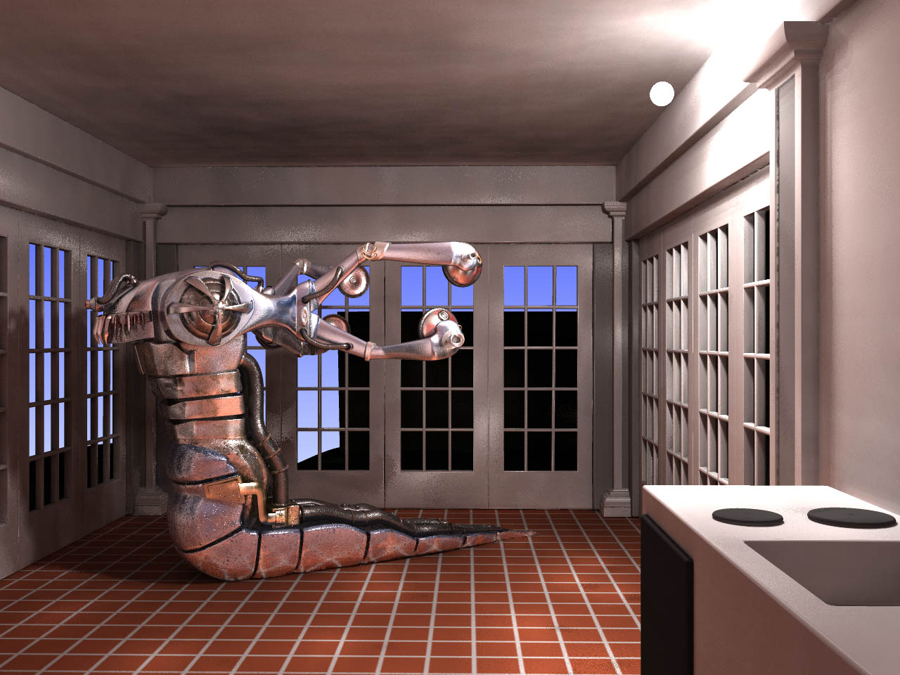
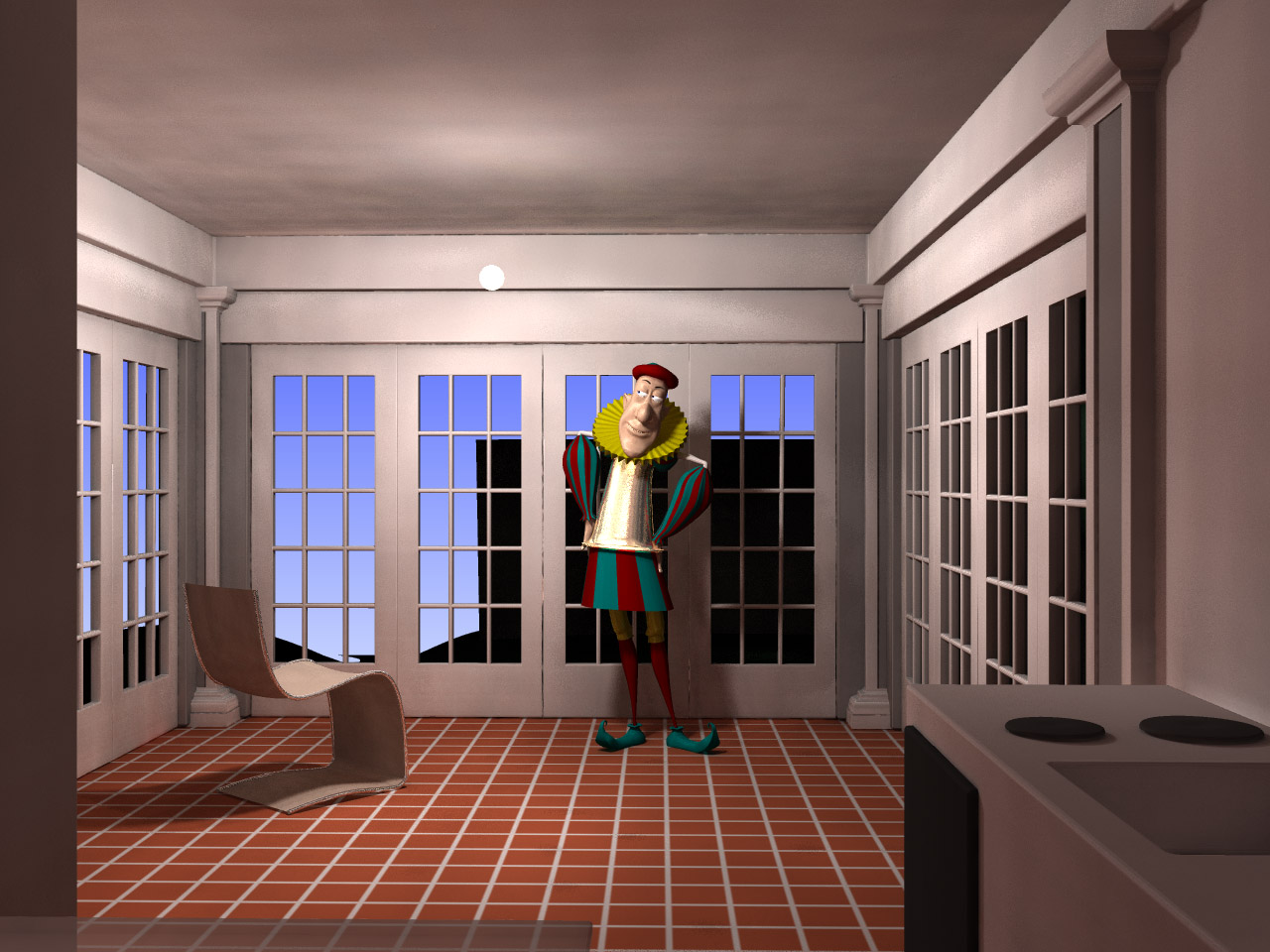
I dropped some old models from the AM CD into my tiny house room lit with radiosity. All the lighting is just that one bulb light near the ceiling.
Mach 5 Racer:

BioBot:
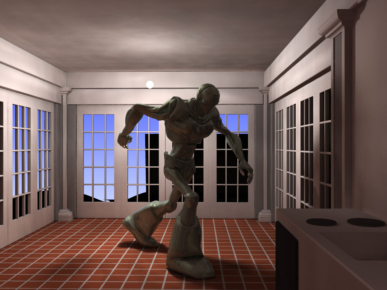
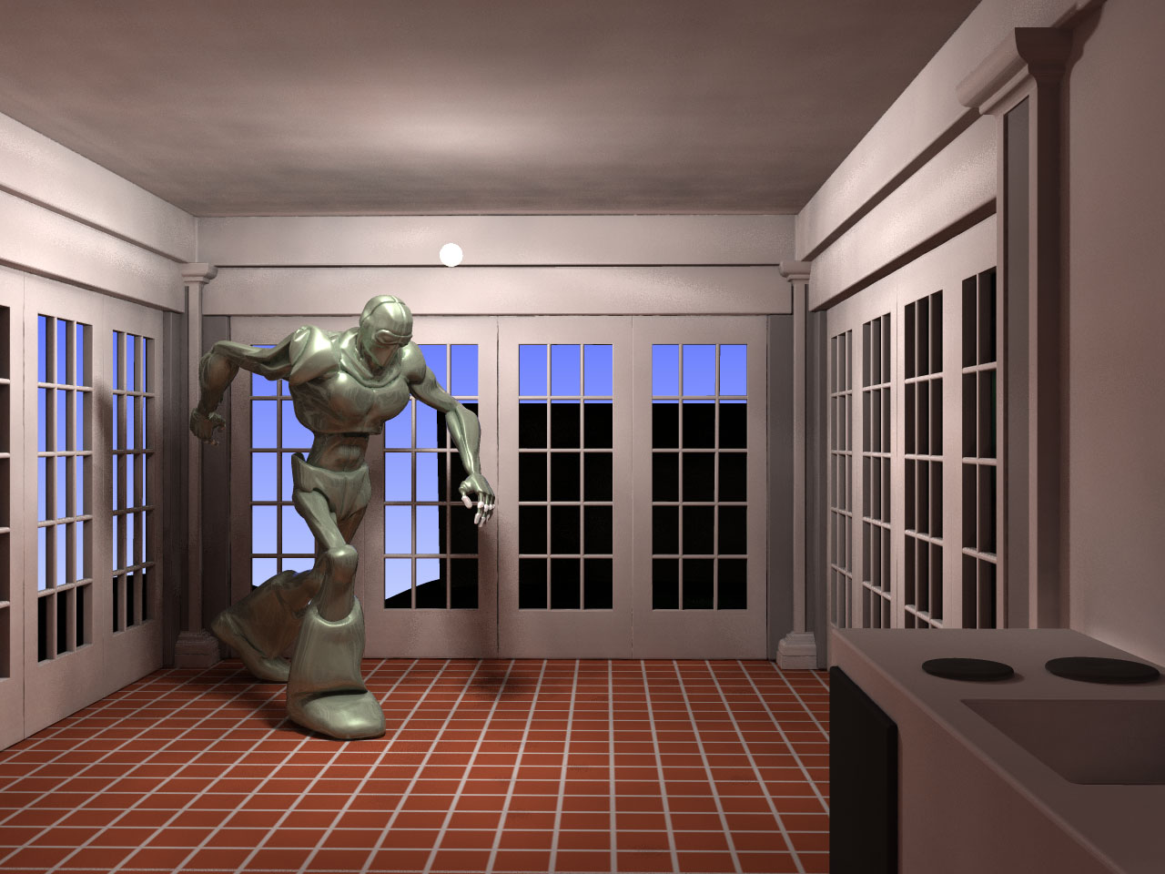
MotorCycle:

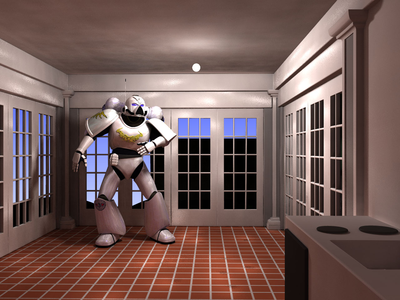
Janitor of War:
Space Marine. Something about the surface specularity on this model and the previous one is causing the conspicuous bright spots in the room ( I think).
-
 1
1
-
-
I have not read the particulars regarding this contest but you may be interested.
Quote...The 50th Anniversary release will also be celebrated as Pink Floyd invite a new generation of animators to enter a competition to create music videos for any of the 10 songs on the iconic 1973 album...

-
Here is one of @detbear's characters dropped into my imaginary living room...
-
1
-
-
That is a "hard news" newspaper.
-
And to think that some people question the need to keep a caged lion and and a badger in one's back yard at all.
-
10 hours ago, Roger said:
Is that Slugworth from Charlie and the Chocolate Factory in the newspaper there? Sure looks like him.
Different actor, different century.
Wilfrid Brambell seems to have already been a well-known TV actor in Britain by 1964 but outside of the UK he's just "that guy in 'A Hard Day's Night'"
According to Wiki he starred in a Broadway play that closed after one performance. Ouch.
-
A camel cookie!

when I add an action to a model in choreography it has transparent parts?
in Open Forum
Posted
Can you provide a sample PRJ?
The description is a bit unspecific.