


robcat2075
-
Posts
27,846 -
Joined
-
Last visited
-
Days Won
348
Content Type
Profiles
Forums
Events
Posts posted by robcat2075
-
-
Here is one I got at an ASIFA sale in L.A. long ago.
It's a dancing bean from a Van Camps commercial.
It was $15 but I'm sure it has appreciated since then!

-
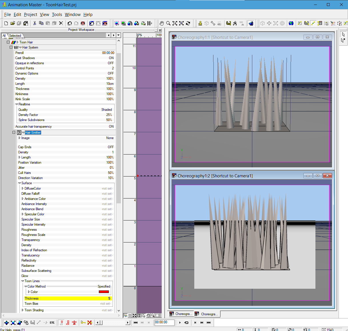
Hair can render faster if
- it has Cast Shadows OFF
- it has fewer Control Points
- it has Accurate Transparency OFF
- it is lit with z-buffered lights instead of ray-traced lights
-
Chuck, Have you found which cartoon yours is from?
I dimly remember the dog in mine but I haven't done a PP survey to find a title.
-
Roger, since you have the broken part... you should model it!
Then someone could know if it was printable.
-
Displacement maps are tricky to get good results from.
Perfectly vertical sides will be impossible. The edges of any form will need to have some slope. The more slope the better.
Straight lines and sharp edges tend to show off the worst of displacement maps.
Zero width lights seem to be a problem. Use a ray-traced light wide enough to cast a discernible penumbra.
I'm not sure what causes the wavy lines but my work-around is to render at 2x or 3x or 4x the normal res and then scale that down to normal size in post.
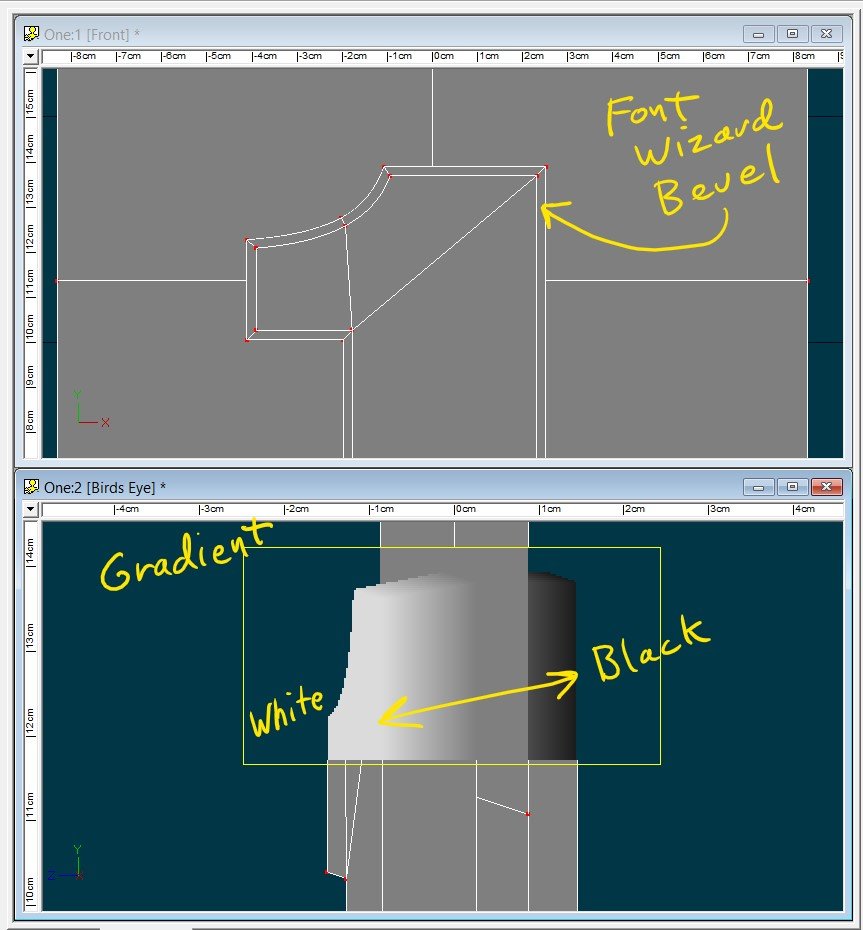
I used the font wizard to model a "1" with a wide bevel and added a flat plane to serve as a background.
I put a black-to-white gradient on it and shot that with an orthogonal camera to get my displacement map. I used OpenEXR but PNG16 will work also.
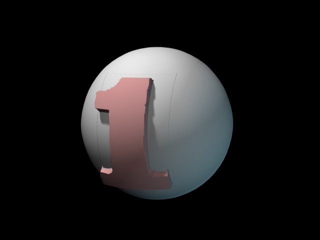
I decaled that to a sphere.
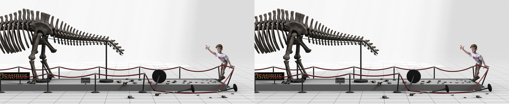
This is rendered at 480p with 16 passes
This is rendered at 1440p with 2 passes and scaled down to 480

-
Hi Teo,
Can you post a sample case we can look at?
-
Quote
The second field signifies "attached" (T/F) to another CP
A better description of this true/false second field is "Position taken from another CP")
If 1, (true) then the fourth field gives the CP number this CP's position is taken from.
If 0, (False) then the CP position information will be explicitly given in the fourth and succeeding fields
-
You could have him swoosh his head from one side to the other on "alllllll"
-
A 1 in the 512 bit place means the CP is "locked"
-
If I replace 262145 with 1 that means the CP has
0000 0000 0000 0000 0001 in the first field instead of
0100 0000 0000 0000 0001
With that first 1 missing the default bias through the spline is parallel to a line drawn through its two neighboring CPs. I believe that is an old style that previous versions of A:M used, now named "perpendicular normals"...
With the 1 in place the default bias is derived somehow differently. It is not parallel to the neighboring CPs. This modern result is called "biased normals"...
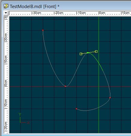
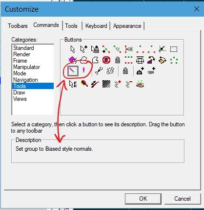
The choice of Biased or Perpendicular normals can be selected in the modeler with the same-named buttons which can be added to a toolbar from the Tools>Customize>Commands menu...
-
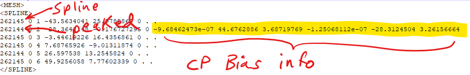
The first field is some set of binary flags
The second field signifies "attached" (T/F) to another CP(EDIT: A better description of this true/false second field is "Position taken from another CP")
The third field is the CP#
After that the fields are data and can be of varying meaning
In line 26 the 4th, 5th, and 6th fields are X Y Z locations
However, in line 27 there is a 1 in the second field (attached = true) so the 4 in the 4th field tells what other CP is it attached to, no X Y Z is supplied
the space-dot-space-dot seems to mean "apply defaults for CP bias"

-
262145 in binary is
0100 0000 0000 0000 0001
262144 in binary is
0100 0000 0000 0000 0000
that is too much of a coincidence for that to not be a binary number where each digit stores some true/false value.
The 2.5 byte size would odd, probably not the full possible extent of the value. The real value may be a four byte integer
-
Hi Charles,
Very cool stuff in that video! Very impressive all around.
I recall doing some slight investigation these numbers...
The first number seems to contain flags about properties of the CP. It may be a binary number with on-off flags.
The last digit indicates peaked/not peaked
the dot dot is a placeholder for CP bias info when there is none
-
@ChuckGram and I briefly got onto animation cels at LAT.
Here is my possibly authentic Pink Panther cel I tried to send a pic of but couldn't during the show...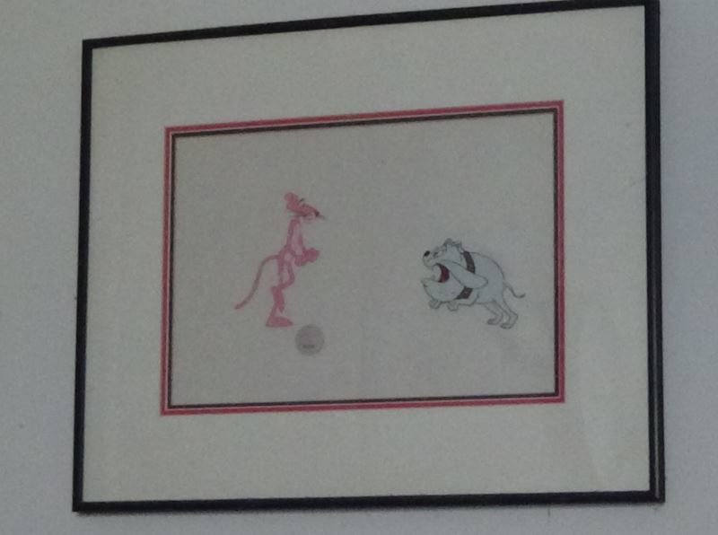
It's actually three cels, Panther, dog and the white rope Panther is holding...

It had a "Friz Freleng" signature but the ink on that has faded to invisibility.-
 1
1
-
-
I guess you are stuck. Since no program presents everything you want and since you have to make some accommodation for what it doesn't, you will have to choose the one with the work-arounds you can live with having to do.
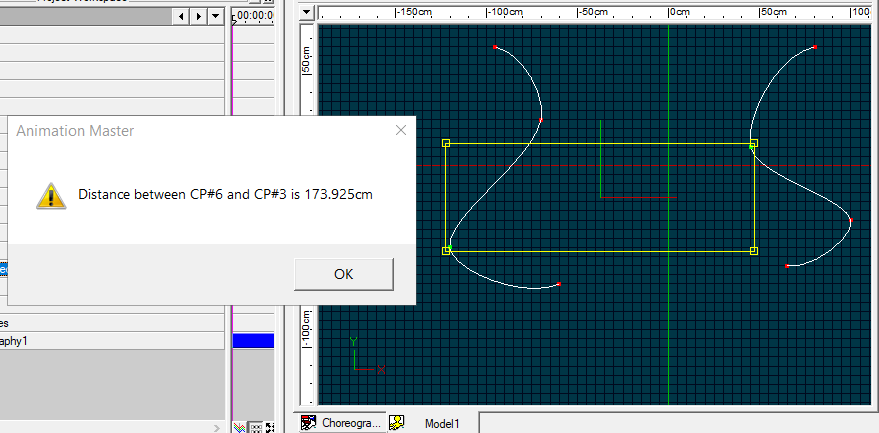
The grid in the modeler can be set and re-set to any increment you want for precise CP placements with Snap to Grid.
The "Measure Distance" menu option finds the distance between any two CPs.
-
You should make the stem wag.
-
Hi Nate!
I recall Martin saying years ago that A:M wasn't built to be a CAD modeler and it wasn't a niche they intended to pursue. You've been warned!
None-the-less A:M does have strong OBJ and STL exporters and a number of A:M users are using A:M to create objects for 3D printing*.
True modeling Booleans for Splines is a big leap. If you need it, I suggest modeling in A:M as if you were going to use its render Booleans, export the base model and the "cutter" as separate OBJs, then import both into one of those programs that people use to fix polygon models for 3D printing and do the Boolean cut in that.
*Our Image Contest Medal is modeled in A:M, 3D printed in resin, then the resin print is used to cast medals in pewter...-
1
-
-
Sorry you're having trouble, Benjamin! I'll inquire.
-
Try these. I reconstructed these from screen captures...

-
Another option might be to craft an image that appears as if it is tooned to use as a hair particle
-
By "particles" you mean hair?
I can get hair toon lines by setting Toon in the Hair surface props. It doesn't seem to obey color and thickness unless those are set in the render settings.
(Notice that toon lines only render if they have patches behind them.)
-
Which video?
-
That is snazzy, Myron!
-
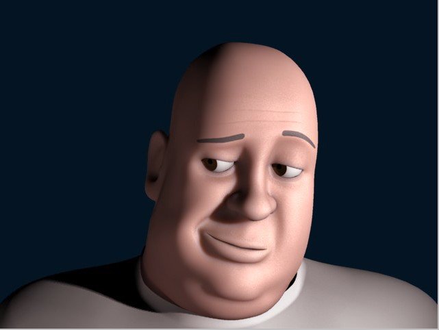
With forehead lines...
Rubik's Cube considered
in Work In Progress / Sweatbox
Posted
Here is the Rubik's Cube that we rigged at LAT today...
Now that we've thought this through once, there are several steps we did that I think could be simplified or omitted.
I also think @Tom's suggestion about a set of Pose sliders might be doable.
Perhaps we will re-visit this topic at a future LAT.