oakchas
-
Posts
1,342 -
Joined
-
Last visited
Content Type
Profiles
Forums
Events
Everything posted by oakchas
-
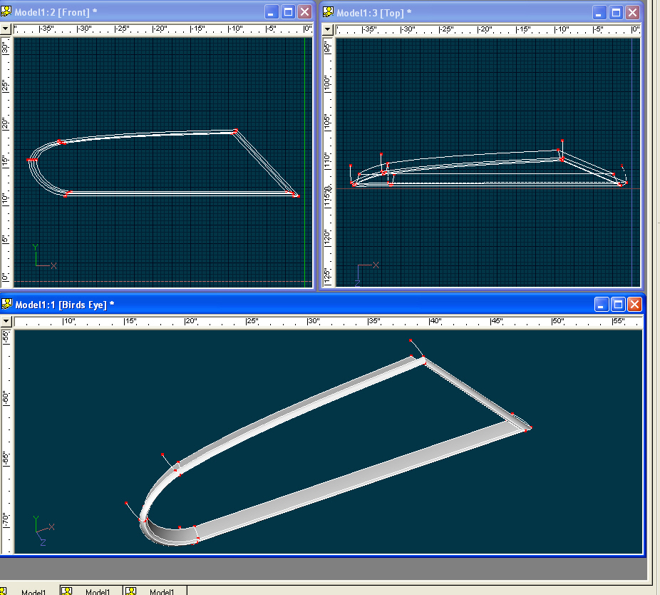
Yep, you are... 'cept for one thing! I pulled a fast one on ya...Where I've circled the cps, on the original loop, before I did the extrusions, I tweaked the bias handle to make it "curvier" where it goes upward to the next cp. Didn't mean to do that to ya, but once it was done, I thought I'd see if you caught it and asked a question... It's a really small tweak so not easily noticeable. Mine has a slight "crease" where that spline goes from front to back, too but it's covered by the shaded wiremode spline. I may have to tweak it a bit more to reduce the "seam". [attachmentid=17163]

-
Okay, I've got all the rotos set correctly. And am going to try to attach the zipped prj file so we're all on the same page...my ISP was down this morning, so I'm getting a late start. Here's the zipfile:[attachmentid=17153] Now we can start splining... sorry for the delay! I've started from the front view. I'm outlining the right portion of the grill opening (on your left as you look at it in the front view (numpad 2)). Then, I go to the top view (numpad 5) and select all of the the closed spline. Holding down the #3 key on the keyboard (not the numpad) I drag the spline to the front of the car. Holding the #3 causes the spline to move in the Z axis only. the opening is not on one plane so I move a couple of points that are on the top of the grill opening back in the Z axis. And, I've peaked (P key) the two right most cps nearest the centerline and the one on the bottom left. That'll do for now, we'll have to tweak them more later. Now i start extruding, the E key will do this. I extrude back a little bit (about an inch and a half for now, and scale (S key) in all axis smaller. I highlight the original loop, by selecting one point, and hitting the comma key, and extrude forward a little bit (1/2 inch or less) and scale larger in all axis a little bit. This starts the "bevel" around the edge of the cowl. Now extrude this ring once more toward the rear and larger, then this new ring once more towards the rear and lrger again... go back towards the rear more than an inch or two. select this new ring and delete it... it will give us some hanging splines to attach as we need later. this is what it looks like: [attachmentid=17154] That's all i have time for today, sorry. Try to match what I've done I won't load this progression of the project 'til tomorrow around noon. batmobile_project1.zip
-
me too! Tomorrow, we should start some splineage. But I'm trying to make it so that we cover all the bases to help any real newbies, too. 'Til then!
-
Curtis, I love the first of these two latest! You are having fun! And making it fun to view... What's your editing program?
-
That is correct. Gawd, I hate that! This one always confugles me... Here's why: That's how it's done in engineering. The quote is from Wikipedia. In choreography/filmography Stage left is to the audience's right and vice versa. (hit hammer on head smiley here) (from which view, you might ask... but please don't, I might hurt myself!0 So, we're looking at the left side of the car (the driver's side, on this side of the pond) from the left. Engineering says that is the left view. Camera view, though, is the opposite. See: the Art of Animation Master pp. 83 So, we'll use that 'cause that's what the manual says. To avoid confusion I always think of it as I am looking toward the farthest side (in this case, the right side of the car) so it is the Right view, correctly. Rightly so! Arghh! Yes to the question of orienting the top view to have the headlights pointing upward, Northward (this way^^^) ! hehehe! Are we having fun yet? That was a joke, son, the headlights should point "South" I couldn't edit last night at work.
-
Dhar, T-Dogg You're welcome to follow along, and even to pitch in with opinions and ideas (I do want the actual modelling for this project to be done by T-Dogg and me, but we are sure to run into a few trouble spots along the way where we'll need real help from bystanders. I hope that's okay with you, Dhar.) I only regret that I haven't yet gotten to splinage. But looks like we can get that started tomorrow. T-Dogg, I've only loaded the front roto into the modeling window... See if you can figure out how to do the side view Left, by loading the left Roto into the left modeling window and placing markers at the length and height, and scaling to fit... I think this will be a fun project... And I know Jin Kanza(sp?) was trying to get the same thing accomplished maybe it will work this time.
-
Will Sutton, Zandoria Studios, had made his PDF for the Tech Ref book he published available (but it was unprintable IIRC) The tech ref is in the form it's in. Best bet is to buy the book, though it's a slight bit out of date.
-
Here's the project so far: [attachmentid=17130] And that's all I've got time for right now... more tomorrow. Okay... hey wait a minute... this got moved to the Animation:Master forum... we won't be able to post pics, screenshots, just zips.. This really might work better in a forum area where we can post jpgs etc. I mean I don't want to exclude anybody... And I think, it might be a good learning experience for alot of new users... Maybe we can put it in WIP at least? BATMOBILE_1.zip
-
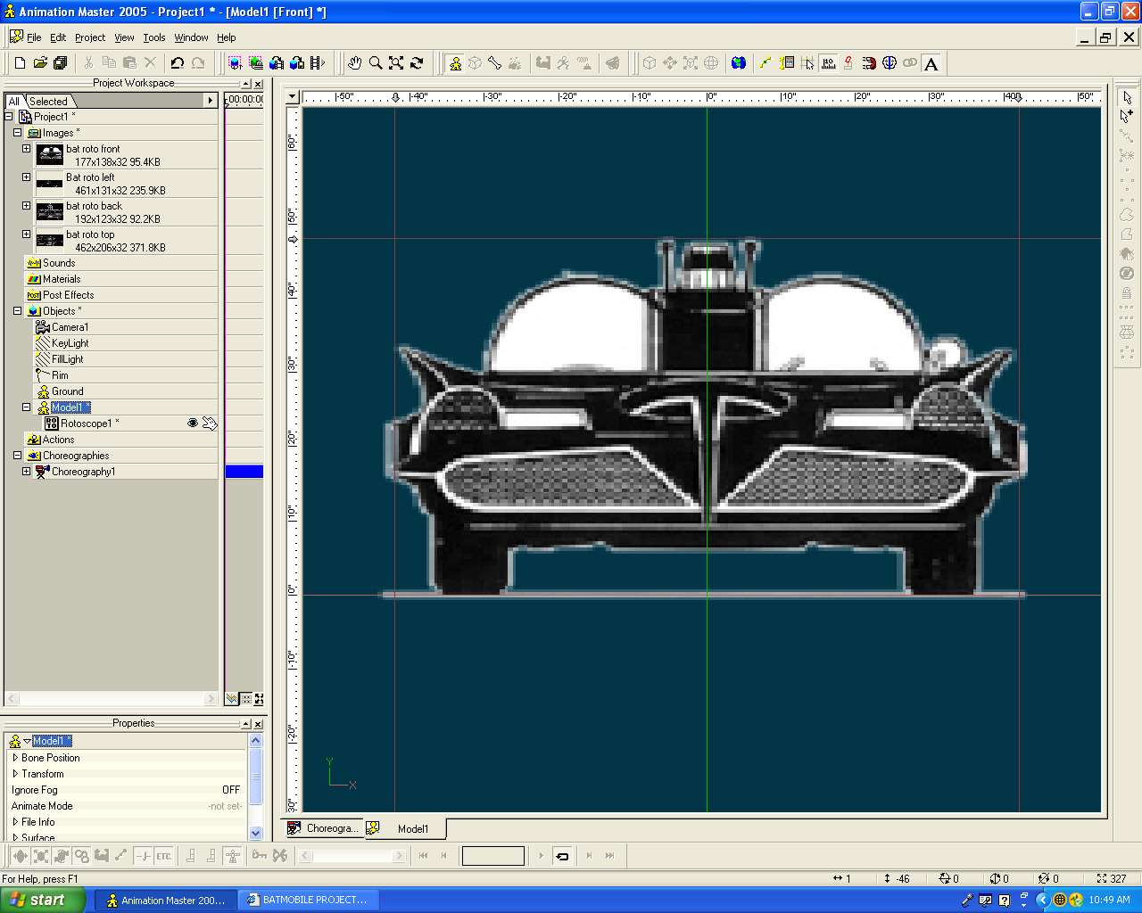
We've got to load the rotos that you gave me... I split the views apart in a photo program, and made the white background transparent by saving to a 32 bit targa file... It should make it easier to see the splines. Then in your front view modeling window, zoom out 'til you can see the 45 inch marks on the ruler at the top. Place a marker at 42 in. on each side of the 0 line. Batmobile is 84" wide. Place a marker at 48" above the horizontal zero. Once each marker is placed, you can set it exactly by hovering the cursor over the grey arrow and right clicking, this will give you an option for marker settings, click on that and set the vertical markers at 42 and -42 and the horizontal marker at 48. Now, right click on the Images tab in the PWS (Project Workspace) and click on import your front view then do the same for all the rest of them. Now we place the first rotoscope: bat roto front. 1cclick and drag it over to the modeling window when you release the mouse button, it will ask if you want to decal or rotoscope, choose rotoscope. A little Batmobile will be in the middle of the screen. you may have to zoom in to grab the handles. Zoom this til it fits about 1/4 of the window. then grab a corner while holding the shift key and start proportionally scaling the roto. you'll do some zooming in and out to get it centered and in the right place. To move the roto to where it belongs, grab it in the middle with the mouse and drag it. You want the tires to just sit on the ) line. When you get it close to the correct width the fin points will just be touching the vertical markers. Now you'll notice that it's too tall. click the center handle of the top of the box and drag it down til the turn signal lights just touch the 48" marker. it'll look like this: [attachmentid=17128]
-
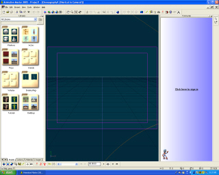
S'okay, I'll get us started today and you can follow along. First things first. The default setup for A:M doesn't work best for me... once you get past the first few exercises, you don't need the library much and the community window doesn't work for me. I'm on version 12v+ and here is the default screen: [attachmentid=17127] I'm gonna change that by: 1.closing down the community window and the libraries window 2.click on View (on the menu bar across the top)and click the Project Workspace and then click on View again click Properties line. One other thing, I open View one more time and click on Workbook too, that puts all the major window tabs visible at the bottom of the screen (Choreography is the only tab there now). 3. right click on the Objects tab in the project workspace on the left and click new then model on the flyout. That loads the modeling window, and by default, the ruler's in centimeters. Centimeters are great 'cause they're divisons of 10, easy to figure out (once you get used to it...) But, our BATMOBILE is Union Made In the Goodl ol' USA and was made in inches so we gotta change that! So, click on Tools, Options. That brings up the Options dialog, and we're gonna go to the Units tab and change the units of measurement to inches. Then click on the Modeling tab and change the 1.97 inches in the grid spacing box to .5 (you don't have to put in the " mark). That should be accurate enough for now. click OK. 4. Okay that's a good start let's get to splining!
-
THAT was an understatement! This site has EVERYTHING on this Batmobile... T-Dogg... Just how far do you want to go with this? We won't be lacking any detail, that's for sure! I can hardly wait to get started! So, join us tomorrow, Same Bat time, same Bat channel!
-
That's an old wive's tale... this has been the solution for me a couple of times now. This is not one of those things a person wants to become expert at. But, ya gotta do what ya gotta do.... 1 quart 3% Hydrogen Peroxide 1/4 cup Baking Soda 2 tbsp Dish Detergent. The stuff for washing dishes in the sink, not something for dishwashers. mix in a bucket, 'cause it will foam... you want it to... we need to generate oxygen... try to wash the dog with it still foaming... (the wash, not the dog's mouth!) interesting what you learn in an animation forum, huh? But while I have a minute, here at work, I'm gonna go look for some more Batmobile pix for tomorrow's splining... Well, I didn't have to look far! the same site has detail shots of most everything on the car... this will be a huge help for accuracy as we get started...
-
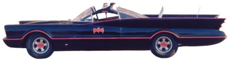
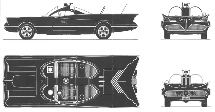
Whadda ya know? type "batmobile speciifications" in google... and the first link is.... http://www.1966batmobile.com/spec.htm Curb weight 5500 lb Wheelbase 129 in. Length 225 in. Width 84 in. Height 48 in. Fins 84 in. And, I can nab that pic as another reference! [attachmentid=17115] Well, that's my hour for today... Didn't even get to open A:M... And I was working under extreme conditions, too! One of the dogs got "hit" by a skunk last night when I took him out after work... and even after a bath in the "right stuff" there's still that wonderful aroma of skunk wafting about in the air! Yecchhh.
-
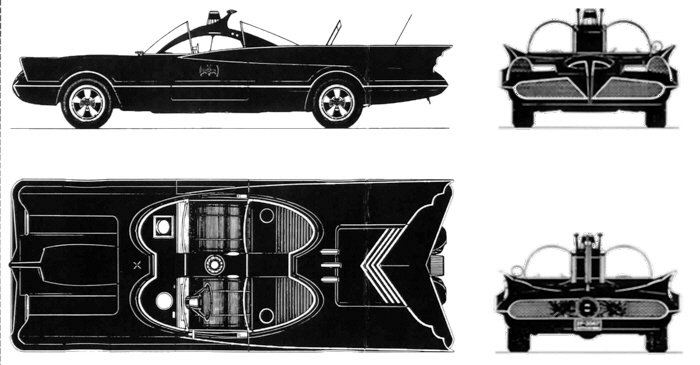
The first thing I notice is that the front and back views are not at the same width as the side and top views... gotta fix that. But, the height is right... hmmm. okay, I've fixed the width on both front and rear to be very close to the width of the top view in my photo program. [attachmentid=17114] Now I gotta go to google to find the actual wheel base or overall length of the real Batmobile surely there are specs out there in google land.
-
This topic will contain the modeling efforts of T-Dogg and oakchas on an old style Batmobile. Basis for the project: T-Dogg is new to A:M, having learned some 3D in another (ecch! polygons) program. oakchas has used A:M off and on for years, but is trying to rebuild his skills. We'll be doing this in ver 12 as Charlie (oakchas) hasn't yet upgraded to V 13 But, I will before this project is complete, so maybe we can light it using AO, and use some of the cooler new features in v13, too. T-Dogg chose the subject, the vintage Batmobile. So, let's get started. Here's the roto that T-Dogg supplied: [attachmentid=17111] First thing I'm gonna do is make a new directory in my hard drive and label it Batmobile project. Then I'm gonna copy this pic to it. Then I'll split the graphic into equal sized views in a photo program to import into A:M. All progress shots and details having to do with the creation of this model will be posted here. T-Dogg don't forget... if you save the model in V13 I can't work on it... 12 is forward compatible, but 13 is not backward compatible! And heeere we go!
-
T-Dogg, You're on! This will allow us to use a alot of the features of A:M: Cookie cuts for the grille, bump maps, ooooh this could be fun!.... I'll move this roto over to the new thread in this topic. we could use some photos too, just as reference to get things right but the photos don't have to be roto views... this will work nicely. I'll devote one hour a day to the work except when I'm off work(during those times real life projects interfere, and I have an odd schedule) but we'll "git 'er done." It would be really nice if we could finish it in time for the mechanical contest, but let's not count on that... We'll just give it a good effort and finish it when we finish it. This works for me, if you are sure of your commitment to the project! Let's GO!
-
user posted pix on Xtaz's tute are broke.. just a head's up...
-
Rodger, Thanks! I'll give that a go. I haven't had much time of late... and I really would like to get this one down...
-
Steve, You are doing better than I could. That said, will the wires here help? another "girly" yet another Look at the spline efficiencies here! And, aren't they beautiful girls?
-
Okay.... No rotos. Whatcha got? What have you modeled in your other program? If it's all people, I'm gonna be in trouble deep! But, if it's all you got, I'll try anyway, and we'll learn it together. My thinking here is that people, realistic people anyway, aren't all that easy to do. But, I think there are a lot of workarounds with A:M that we can use to make it happen. To say nothing of the plethora of tutes out there to work from. And, when we're done, I think (hope) they'll look better than they did in your previous attempts (not because I'm a whiz at this by any stretch, but because two heads are better than one). And, if we do it out here in the open (in a single thread in this new users forum), we'll surely get commentary and advice from the real experts. If it's not people, but animals, yikes! That can be tougher yet. No matter, it can be done. Now, if you really want to learn to do something mechanical, we can do that instead. So, pick an object (organic or mechanical) that you really wanna do. I will place no limits on it except this: we must see it through to the end. Warning: In the end, you may hate the object... Not for the look of it, but for the work you put in it. It may seem a chore at times, you (or I) may want to quit. We will not quit on it 'til we are both satisfied that we have given 100% and it is the best we can do. Some things are over done (like cars and spaceships, dragons and dinosaurs), but don't let that be your determiner. Pick it, we'll do it. Post your idea here, once you've decided what it is to be, we will start a new thread here in new users rather than WIP so that other newbies will see it. Ball=your court... choose well, grashopper!
-
I have had some difficulty with Mr. Walasek's (sp? from memory, probably wrong, apologies) DXF plugins, as well. But it was not really important enough for me to pusue further (tho I should). That said, I understand that you worked hard to create other models in another program. And, I understand your desire not to lose that work. Question: Are these mechanical models, like cars or spaceships, something made of metal... or are they organic models, like people, animals, creatures, or plants. Reason for question: Modeling with splines (and the reulting patches) is so completely different from poly modeling in so many ways. If you are really going to try to make A:M your 3D modeling, animating, and rendering program of choice, then it might be best if you "slip the chains" of poly modeling sooner rather than later. A:M is really like "thinking outside the box" (a box is a polygon after all). But building with patches rather than polys allows you to make truly smooth surfaces (rather than faking them or averaging their surfaces as a poly program has to do). So, building a box in A:M is simple: Make 6 flat patches. That's pretty similar to a poly program, no? But wait! Make a sphere in A:M... oooh... Draw a curve and lathe it. 4-6 subdivisions, and it's smooth... How many subdivisions does it take to make a smooth sphere in a poly program? You may do it with as few as 4 or 6 as in A:M but the software will compute many more to make it appear smooth. Tell you what.. I'm kinda renewing myself in my own A:M skills... So, load rotoscopic pix (top, side, front, back, bottom) of a mechanical model you made in your other program. Starting Tuesday, I'll try to help you model it in A:M... Only one thing.. We have to share the finished model files with the community. Oh, and one more thing, we gotta use V12, I haven't upgraded to 13 yet. Think about it, and let me know here, Mr. Dogg. Heck, I'll even try to use the conversion plugins to bring it over... but we gotta do it "straight" in A:M as well. That way, we learn together and share the experience. Fair enough? Let me know.
-
But really, with simple models like this especially in A:M, you are not "far from building" your own models... Look at the TAO A:M booklet that came with the software... there is a tutorial in there on how to build a fighter plane... and there is a video of it >. About the middle of the page (exercise #10) Now, the Zip file is 93 MB, so you might want to let your pc download it over night... or download the smaller chapters and work on it a little at a time... It's not as hard as you might think! And real planes tend to be "curvier" than "space ships" so real planes are harder to build... Have fun... and give it a shot!
-
More online Demos (Please Help with DL times)
oakchas replied to a topic in Work In Progress / Sweatbox
Wow Greg, wish I had this connection at home.. loaded instantly here at work.. and continued to play thru without stopping to catch up! Look forward to the synched sound.. It's really noticable for me in the alien song "mov" and the "building of" segments. I think this is a T1 connection. BTW -
Here's the bump map that I used on a felt fedora (hat). [attachmentid=17016] right click, save target as... hope it helps, though it may not be dense enough for the jacket. And the jacket may have a weave pattern that would be visible up close. That said, if you're going to animate him, you won't really need this fine a texture, as he'll be moving all the time.
-
Standard/ pixel wXh/ FPS/ additional info HDV 1080-50i/ 1440X1080/ 25 FPS/ PAL(interlaced?) HDV 1080-60i/ 1440X1080/ 29.970 FPS/ NTSC (interlaced?) HDV 720-25p/ 1280X720/ 25 FPS/ (PAL) progressive scan HDV 720-30p/ 1280X720/ 29.970/ FPS (NTSC)progressive scan That's the defaults on a video editing program I have for HD HTH