Eric2575
-
Posts
2,615 -
Joined
-
Last visited
Content Type
Profiles
Forums
Events
Everything posted by Eric2575
-
Ken, your toe looks like it has arthritis...hehehe
-
How do I get from one to the other?
Eric2575 replied to Eric2575's topic in Work In Progress / Sweatbox
Thanks David, but I am looking for a less digital approach. The panels look great, but too perfect for a sub build in the 1980's. I also need to learn how to paint textures, etc. Hey Brian, could you magnify that a bit, my eyes are somewhat bloodshot from lack of sleep -
How do I get from one to the other?
Eric2575 replied to Eric2575's topic in Work In Progress / Sweatbox
Off course you meant nice detail on my unfinished sub, right? Not that "other" sub with all the little bumps and rivits and seams and interior detail and Nemo figure and ......wait, maybe you do mean that "other" sub.....ooooooOOOHHHH, just you wait and see what I can do with AM and no sleep for 48 hours...hehehehehe. -
I played around with bias and magnitude and got even better results. Getting a good nights sleep can do wonders. Thanks for the tip Rodger.
-
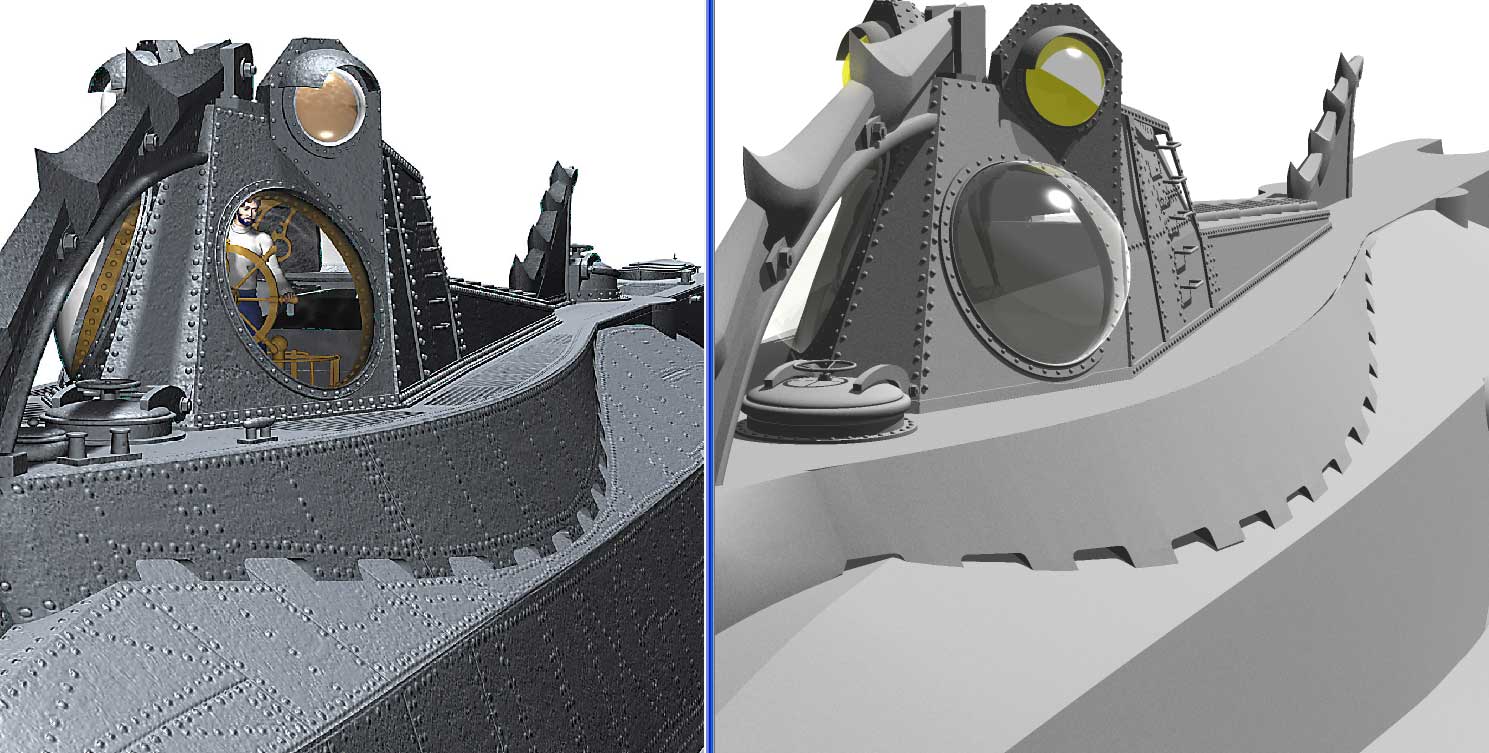
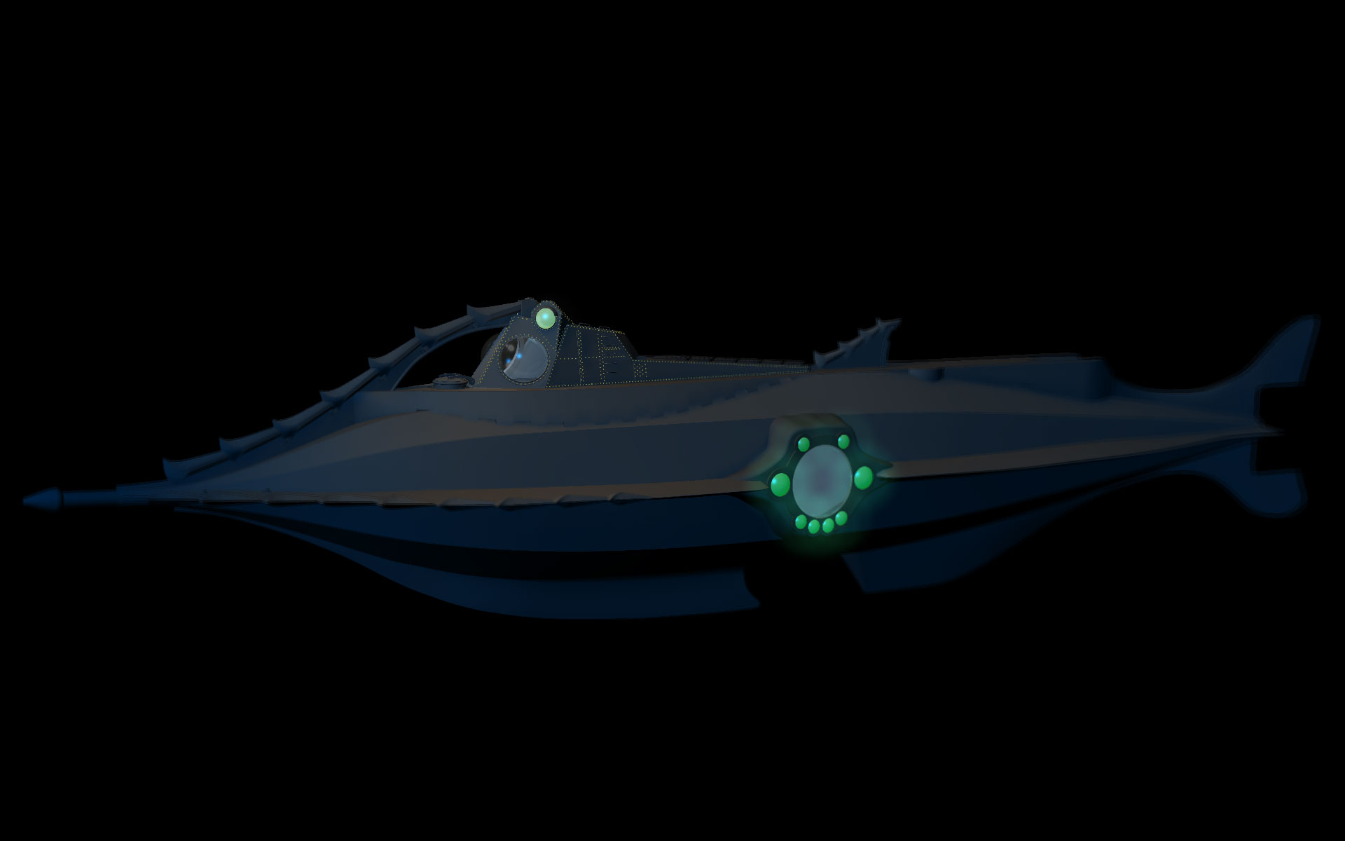
The right one is my first model and I would like it to look like the left one in it's details. I have never done anything like this, so any advice is really appreciated. Correct me if I am going in the wrong direction. Would I take my model apart as in flattening the hull? Once it is flattened, draw the plate lines on it in photoshop and then apply the tga as a decal color map and bump map? The model on the left was done by Fred Kuentz and William Babington. Since the hull is basically an octagon, should I flatten each of the eight hull longitudinal sections, or just half the hull flat? I also wonder how can I achieve any proportional accuracy and spacing when I have to draw hull lines on a flattened piece that is distorted by the flattening? Just when I thought the hard part was over

-
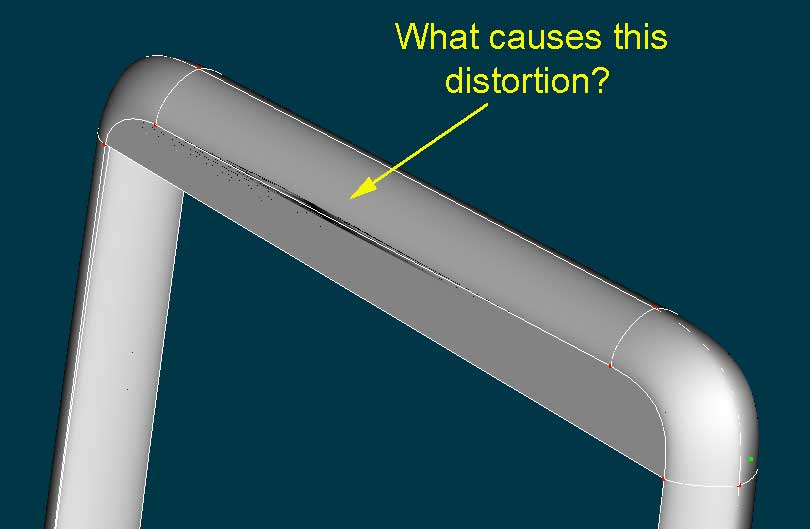
Here is my final attempt for this project. Not perfect, but very doable. Is that a word? This is the rudder for the Nautilus.
-
I started out with a single spline with several CP's connected to form a rudder shape. After selecting that closed loop, I extruded twice. Once done with extrusion, I wanted to stitch the sides together to create the side faces. On my first stitch, I noticed the distortion you see in the jpeg. Normally I see that with overlapping splines, but how can that be on such a simple shape? Two extrusions is all. Also, when I select a CP and pull it away, there is no other one hiding behind it - if that makes any sense. Any ideas?
-
What exactly are UV coordinates and how do you check them? The normals are all facing the same direction.
-
Its' a pretty straightforward 5 point patch. Why is the decal distorting on it? There are actually two 5 point patches on the jpeg next to each other- both distorting!
-
I'd be angry to if I didn't have any legs, the thingy between the legs, hands, buttox...is that how it's spelled?? Did I mention brains??? No, I have brains, just not sure who's? Amyway, looks very smooth, good job. Been down in the sub too long, gotta surface and get some air!!
-
Vern, you are de Bomb
-
Wait till you see it with some proper textures and bump maps. Still have to learn about bump maps. Thanks Rodney!! Wanted to post this pic. Used Photoshop to play with the aura a bit. Can we use Photoshop to do this kind of stuff if we want to submit a model to the monthly contest?
-
I am not getting anywhere. Just to mess around some with bumps and materials, I opened a new project and imported a basic shape out of the library. Then I double clicked the materials in the PWS and made a fractal sum material with black and white. Once this was done, I dragged the material to the model under the objects heading and rendered. Nothing changed. Next I went back to the material and looked for a way to tell it to be a bump material. The only option I found was a "Bump Percent" section which I changed from 0 to 34%. I rendered again, with no change. So I figured that maybe multi-pass was set to "on", which it was. Somewhere I read that some changes don't appear on quick render if multi-pass was on, so I turned it off in the options. Rendered....and nothing. This is getting old.... Ok, success!!! There seem to have been two models in the project, the generic one in every new project, and the one I imported from the library. I applied the material to the wrong model, duh. Now I see the change in the imported one. Time to experiment....Will post a pic of the Nautilus with some bump and other neat stuff soon.
-
That's exactly my point, it has no texture yet. This is my first model and I have never textured anything in my life - haven't modeled naything other than this for that matter. Ok, guys...How would I go about this...bump maps I mean. Do I need to flatten the sub and do it in pieces like a face?
-
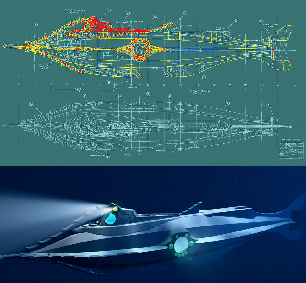
Thanks so much for all your kind words...I had a pretty lousy day and you guys just made it all better Also want to give credit where credit is due: I used Johnl3d's underwater settings to get the cool deep water effect. Thanks John...I hope it was ok to use them...uh, should have asked before I used them...ummm...well...ah...getting that deep sinking feeling... The sub still has a long way to go but it's getting close. I still need to finish much of the detail work and play with bump maps and such. As this is my first model, I am not sure how I would go about applying the general details to the hull. Should I flatten the hull and apply decals? I want to simulate many more rivits all along the hull. Don't need the detail level that I applied to the deck. Figure I can paint some in photoshop and apply as decal. I have many pics of the Nautilus for reference but manily used modified plans obtained over the internet. The Disney 50th Aniversary 20,000 Leagued DVD also helped. The wheelhouse interior will also be modeled as well as Nemo himself. I've made a prelim avi with the sub skimming past the camera at close range...looks pretty cool if I say so myself. Will also try to make a clip with the sub in attack mode, but have lots to learn before that. Here is the wireframe so far and the rotoscopes. Hmmmm, no wonder the sub wasn't going anywhere, it has no rudder or prop.....
-
STUNNING! Great work!!!
-
I wish Charles Babbage would update his underwater caustics for V.11.0 The animation would go great with this model. Comments and critique are welcome
-
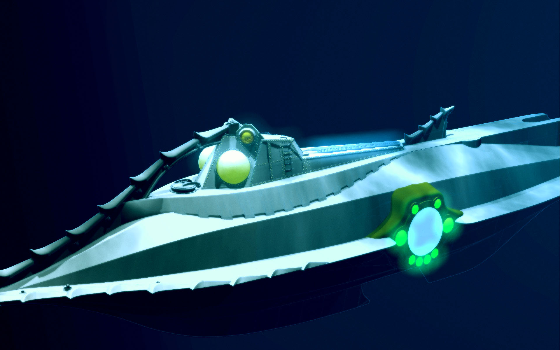
Please, tell me more. I am not familiar with a light image. Here is a pic of what I have so far. I turned down the intensity of the light in the wheelhouse (a bit too much in this shot) and the light in the big porthole in the center of the sub. The sub is a WIP as you can tell. Volumetrics are turned on for the center port, but not for the wheelhouse for comparison. I noticed when I had volumetrics on for the center porthole with intensity at 100%, the light shone throught the hull, not just the porthole. I don't want that to happen. Man there is a lot to learn in AM, even just the little stuff like simple lighting. Also, I noticed that the tail and nose of the sub are out of focus. I have noticed that on several models, although I made sure the near and far focus of the camera included the whole model. What causes the blur?
-
That worked, thanks. Now, two more questions: How do you make a light shine through a porthole? What causes leakage of light when it it placed inside a complex model? For instance, I am modeling the Nautilus submarine and want to have a light on the inside of the sub shining through a porthole to the outside. When I turn on volumetrics for the light inside the sub, the whole sub glows in every direction.
-
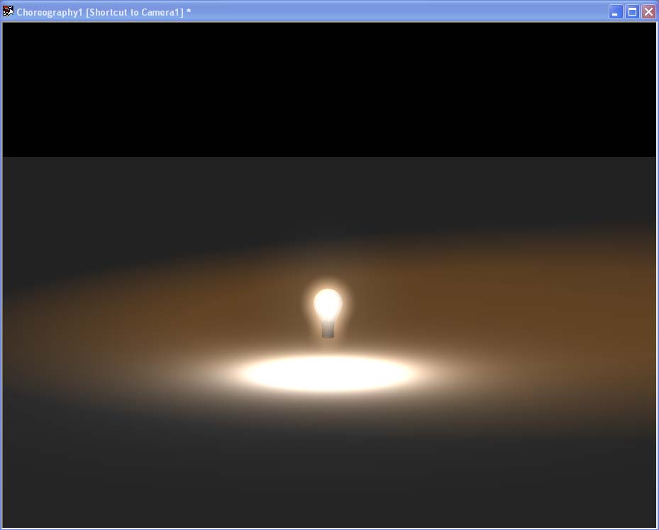
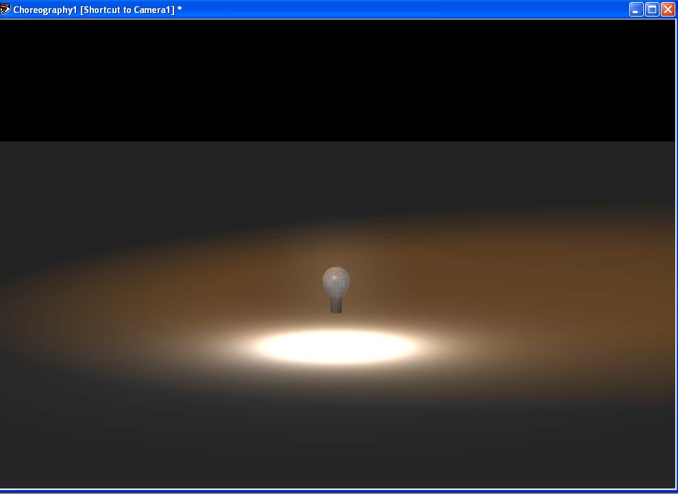
Something trivial I'm sure, but how do you make a bulb or any other self-illuminated object give off a nice glow? The pic has the KeyLight on set to 21% with the FillLight turned off. One new light (set to "bulb") is placed in the center of the bulb model with volumetrics On and intensity turned to 100%. The glow shows nicely on the floor, but the 80% transparent "bulb" model isn't illuminated at all. Am I missing something (obviously), or is it not possible to make a light source shine from the center of an transparent object/model and illuminate the object as well as the surroundings? Please help me shine some light on the subject Gotta get out more often
-
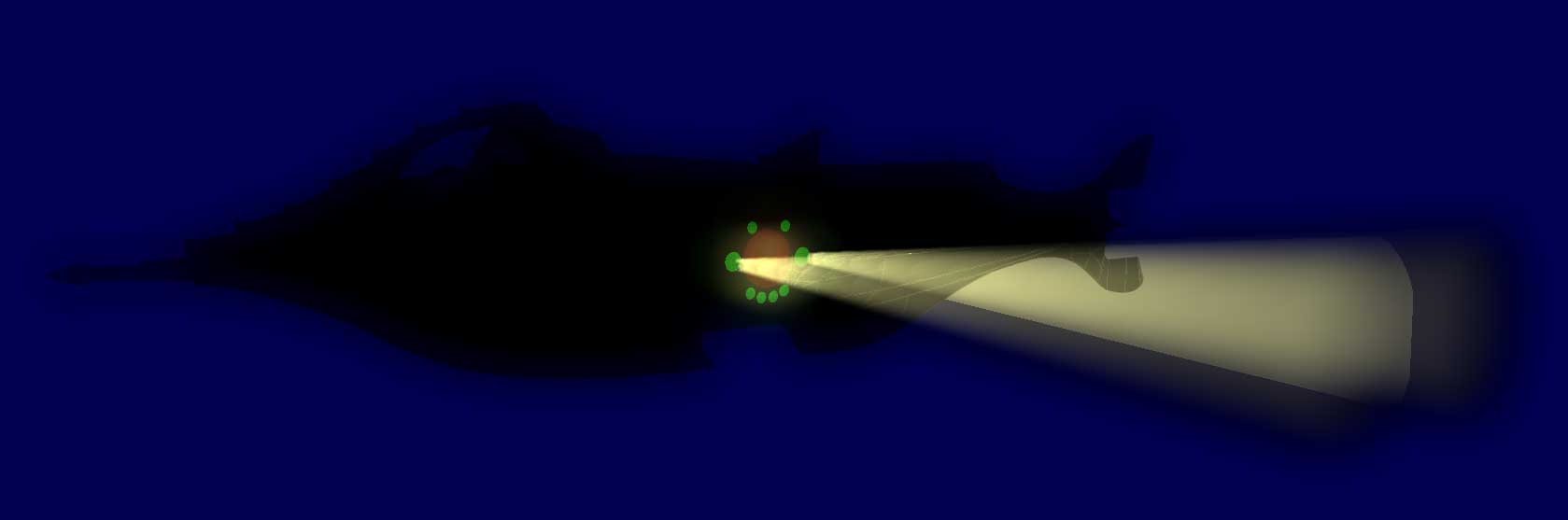
Ken, I've played with softness in the volumetrics but am still getting the sharp contrast. Will try multipass. Wiliam, the objects that the spotlights are supposed to be coming from are the two bigger green orbs on the side of the sub. Ambiance is set to 100 and glow is already turned on. I wish I could find a tut on making spotlights or even how to make a light glow through a window. There is actually another light source inside the sub that is supposed to shine through the bigger porthole between the two spots. For some reason, that is not working at all. Robcat, yes it is the Nautilus. I'll post a small avi soon, check it out on WIP. I'll also try your idea with the background patch.
-
Played with several variables without much improvement. The overlapping beams build up and give an unnatural bright area. What can be done to make it look better?
-
To join, or not to join, that is....
Eric2575 replied to Eric2575's topic in Work In Progress / Sweatbox
You are funny Vern...always like reading your posts. -
There are many instances in a model, when you could simply stick one object into another to make it look like they are one. Take, for example, a wrought iron fence, or a lever sticking out of a machine. Another good example, intersecting pipes. When would you have to join the CP's and when could you get away with the cheat?
-
Zero: You made it quick, easy, and it looks good. We have a winner!!