


Ganthofer
-
Posts
550 -
Joined
-
Last visited
Content Type
Profiles
Forums
Events
Posts posted by Ganthofer
-
-
What program are you using the depmth map in to create the final image?
I'm just curious.
I've played a little with Gimp and Paint.Net. They don't, as Robert pointed out have a proper blur using a depth map. You can't choose the grey value for the infocus depth. So I understand your experimenting to move the white to the area you want to be in focus. But as he also points out, there are problems for some programs to not blur the in focus objects. Like the trees taht are at the same focal depth as your infocus rock. The truck near the ground is infocus, but as it gets thinner and is against the blurred backgournd, it ends up getting blurred. In theory, it should still have sharp edges except where something in the foreground passes in front of it.
Gimp seems to leave an unwanted edge on the out of focus objects (at least on my experiments).
Paint.Net (with the Blur map plugin) uses a grey scale (or alpha or RGB or ARGB or...) as a blur map with white being in focus and black being blurred. It seems to handle the sharp edges of the in focus objects against a blured background.
-
Are you wanting to be able to animate this or are you just looking for a way to create a final with the 5 colors?
I may be totally off on what you are trying to achieve, but this is my take on the problem:
I am assuming since this is showing signal strength, that the Higher signal (e.g. Blue, green, yellow, orange, red) takes precedence.
-Split each of the three maps into the 5 layers (one for each of the strength colors)
-Make then opaque
-sequence the layers Front to Back ( or Top to Bottom) Blues, Greens, ..., Reds
-Render (or flatten) and save (depends if you are ding this in A:M or a Paint/Image editing program)
-set the transparency
-
If you are asking about only displaying the patches that are facing the camera/view. Here is the thread that Fuchur answered, Show Backfacing polygons
If that's not what you are asking for, then you'll have to clarify what it is.
-Robcat2075 beat me to it. I type to slow!!
-
Thanks for the hint.
If you use Firefox (not sure what version it started with - I have 3.5.3), you can drop and drag from the web page to Windows Explorer so you don't have to right-click save image as...
Also there is a plugin (Browse Images) which will increment the number in the web address so that once you open one of the images (http://www.animationarchive.org/pics/zim20-big.jpg) all you do is click the increment and drag and drop from the web to your folder.
-
Here are the terms of Use license from the Darktree web site
-
I am guessing that you turned on "perspective view", no grid or rulers and it's , well, in perspective
If you have the default keyboard short cuts, pressing the \ key should toggle it on and off.
Also it is the Icon between the Bird's eye and the Camera view on the Views toolbar.
If that's not it, any chance of a screen snap?
-
I definitely like Robert's solution, but if you want geometry, try using Steffen Gross' Explode_Rebuild wizard. It will build an inner or outer surface (depends on the choices you make in the plugin) and you can define the thickness. I not sure if it is included with AM or not. Check for E_Rebuild.hxt in you HXT folder.
E_Rebuild instructions
-
Well, shows what I know.
Learn something new everyday, sometimes useful, sometimes not.
Today it was something useful ;-)
-
I could be wrong here, but I think you will need to use a decal for what you are describing.
to make a material scale with your patches, would require, just that, actively changing the scale of the material. Depends on the model and movements, but this would be (could be) quite complicated and may not be practical.
-
In case you are still interested:
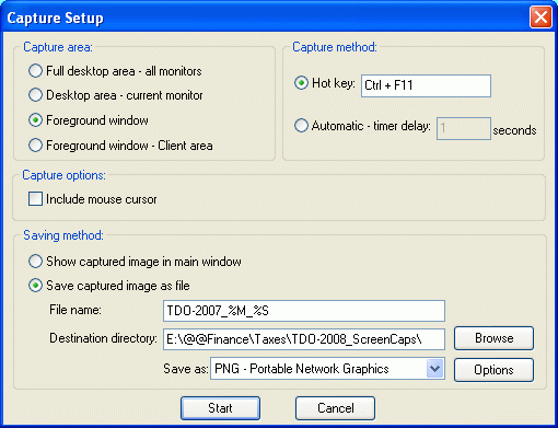
1.start Irfanview
2.from the menu select Options > Screen Capture
3.Configure as needed. (see screen shot made with Irfanview

-
I didn't see you mention anywhere if you were using multipass. I notice that when using multi pass, with the light as part of a model, it shifts the light from where you center it in the modeling window (appears to be affected by the width setting). Haven't done any further investigation at the moment. Just a thought.
-
Irfanview is my preferred program. But Wink is quite useful to.
Irfanview home page (added note from website: IrfanView is provided as freeware, but only for private, non-commercial use (that means at home). IrfanView is free for educational use (schools, universities and libraries) and for use in charity or humanitarian organisations.))
Wink (debugmode) home page download (added note from website: Freeware: Distributed as freeware for business or personal use. However if you want to redistribute Wink, you need to get permission from the author.)
-
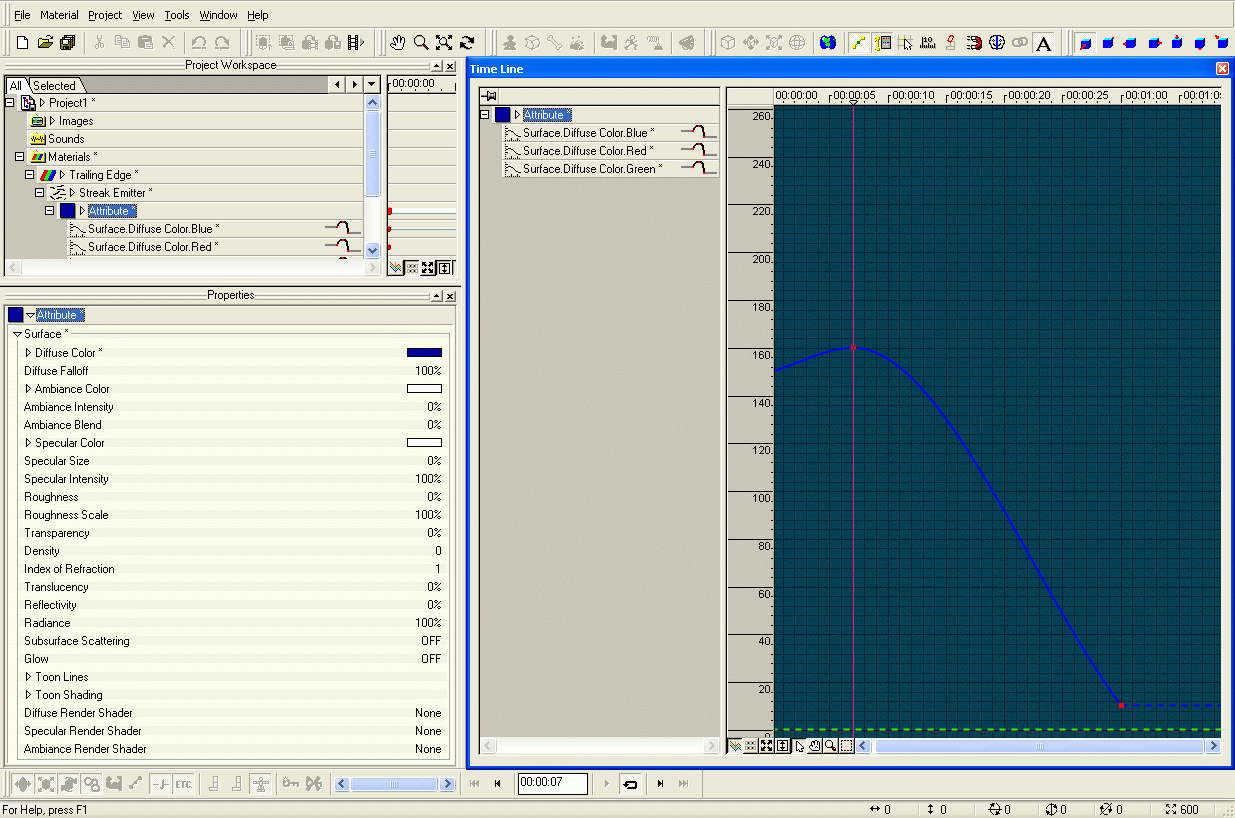
OK, here goes. First see the attached screen cap. Next under "Tools > Options" on the "Global" tab and make sure "Show Property Triangle" (lower right corner) is selected. Also under "View" select "Project Work Space", "Properties" and "Time Line"
-Once you create the material and change the default type from "Attribute" to "Streak Emitter", then click the + in front of the "Streak Emitter" and you should see an "Attribute". Clicking on the Triangle (between the White square and the word "Attribute" will display the "Surface" attribute.Again click the triangle in front of the word "Surface" and you will get all the surface properties.
-Click the triangle in front of "Diffuse Color" and the RGB sliders are displayed. Slide the Red and green to 0 and the Blue to 150 ( or enter it in the boxes).
-Now that you have set the first point for the diffuse color, there will be a + in front of "Attribute". Click it and you will see (below the "Surface" properties), 3 entries "Surface.Diffuse.Color." followed by the color.
-Select the Blue and in the "Time Line" window you should see the Channel for the Blue Diffuse Color Setting.
Try and make it this far and get back to us if you have more questions. And Good Luck.
-
I believe this is the one you are looking for Make a Fake sculpt mode... maybe?
-
Hey Rusty,
I prefer #1, the orange tinted lights don't feel right to me, but can't suggest a better color or a reason at the moment. I can hear a very loooooow bass thumping or rumble and maybe the green mist is pulsing slightly.
If the whole room is somewhat foggy/hazy, then #2 gives that feeling to me, but the room would need to be darker and music/sounds would have to support it.
#3 just seems to monochromatic and bright. Perhaps if the darkest part of the room where pitch black then the lack of color (saturation) would fit the mood you are going for.
For me, it depends a lot on what is happening in the room. Do we just see the empty room or are there people (human or otherwise) in it? I think that maybe there is to much sharp detail visible, which brings me back to darkening the room more.
That's just my 2 cents with the hazy Big Picture I have
Glenn
-
Merry Christmas Wally
First, how are you trying to select the patch to flip the normal? Did you use the Patch Selection tool or the lasso tool or just the normal cursor and select the 4 points?
The only possibility I can think of is, there are duplicate CP's and the actual patch CP's are not all being selected. Did you create this model using copy flip attach?
Check the 4 CP's in wire frame mode by moving each one (then undo), one at a time to see if you have some duplicate CP's/Splines.
Good Luck
-
Hey Steve392,
have you looked in the mbw_conflicts.txt file that is referred to in the error message? It may point you (or someone) in the sirection of the problem.
Regards
Glenn
-
You may be bad in math, but I don't believe you can make a Beach ball texture with spherical or any of the other combiners. The Spherical combiner creates spheres of color with a thickness defined by the ring sizes
If you want to make a beach ball, the easiest way is to make lathe a sphere with 6 Longitudinal divisions (north-south). Make 6 groups, each consisting of the patches between 2 adjacent Longitude Splines. Set the color on the group ( i.e. red, yellow, green, blue, orange, white). You can set the reflectivity and transparency on the basic model to make it look more like plastic if you are trying for a realistic beach ball.
Hope that helps
-
For 3D text, Right Click in a Modeling Window and select Plugins > Wizards > Fonts.
If you have your own custom TrueType Fonts, they should also be usable.
From there you will find many options to play with. There is also the Possibility to import AI files (Adobe Illustrator ?? I believe) by selecting AI (instead of Fonts).
-
First, the question about adding an image to a Model.
-PWS "project work space" > Objects > double click the Object/Model to open the Modeling Window
-display in Shaded(9) or Shaded/Wire(0) (pressing the top row of numbers, not the Number Key pad, those change the View as in top/bottom/right....)
-turn on "Display Decals" (Ctrl-D) the Icon is a Star in a red box.
-There are many choices on how to get the image into/onto the Model:
---Import the image into the Images folder in the Project
---Drag and Drop an image file from Windows Explorer onto the Images Folder in the Project.
---or browse for it once you perform the following step.
-Add an image to the model by one of the following ways:
---Drag and Drop the Image from the Images folder in the Project into the Modeling Window (this automatically makes it a Decal). Position/Resize the Decal and Right Click and select Apply.
---Drag and Drop the Image from the Images folder on to the Model Name in the Project under Objects. Choose Object Type appears and select Decal. Then Position/Resize the Decal and Right Click and select Apply.
---Right Click on the Model Name in the Project under Objects or Right Click in the Modeling Window and select New > Decal. If you have imported images, they are displayed in a list and you also have the option (at the bottom of the list) to browse for the image you want to use. Select the image Position/Resize the Decal and Right Click and select Apply.
Hopefully this will help.
Any questions, ask.
I did this in V13.0l - although, I don't think it has changed.
-
I might be mistaken, but I seem to remember a tool (stand alone or plugin , can't remember) to copy or duplicate material nodes. I'm in the process of cleaning up my hard drives, so I will keep an eye open for it.
-
I replied to you question in the other post, so I won't cover that again here.
Inreverse order:
Yes- you could think of Displacement and Bump maps on steriods. Bump maps only fake the shadow (and I believe the specularity, but not sure)
No and Yes - An easier way to create in PS I don't know. see your other post for suggestions on creating the Bump map (or maybe normal map;)
-
I may not be understanding what it is you are trying to do. BMP's do not have the functionality to contain alpha (transperancy) information.
-I take a series of sequentially numbered bmp (or tga, png ...) and import in the PWS as an "Animation or image sequence".
-In the Chor ( or in the PWS on Objects) right click , select new > Layer and the image sequence you imported into Images (in the PWS) should be selected.
-If you create the layer in Objects in the PWS, you will have to drag it in to the Chor.
-With the camera aimed at the Layer and the default Chor lighting (even with an object behind the layer) the layer renders normal for me.
So, my questions are:
Does this happen in the preview render (render mode and render lock mode)from the camera view?
Is there a transparency set on the Layer surface properties?
Drescripe your work flow (the steps you take).
Glenn
-
You might want to see if you can get a sample BVH file and try it in A:M.
Glenn


new landscape
in Work In Progress / Sweatbox
Posted
I like that idea of a spherical material effector and the double gradient. I experimented with a simple double graient material applied to all objects . never quite worked right.
I'll have to try this method.