wildcard
-
Posts
101 -
Joined
-
Last visited
Content Type
Profiles
Forums
Events
Everything posted by wildcard
-
Project file with model embedded and a quick recording of what I'm seeing on my end. Female_Model1.prj CFA.mov
-
Tried it, no luck with a flawless CPA So for me there is step 6,5) Fix CP's out of whack
-
The screen shot only shows my typical bias handles/magnitude values going to extreme after a CFA. Your work flow is correct and that is how I should be working, however I find it hard to work on only one half of a model and not seeing it a whole model. This also results in my frustration when adding and modifying CP`s and getting them correctly aligned to get them mirrored.
-
that's where you lose me. Don't you want them identical? In most situations yes you keep both sides identical. But I'm pretty sure there are cases where you don't have identical half`s but the majority is still identical. I'm not really pleased with cutting my model up in half again to have it shortly after put back to gather again. CFA for me pairs with bias handles and extreme magnitude values that need to be corrected, specially on larger models. I find it a frustration to re-align CP`s that are not mirrored, fixing CP`s with bias handles/magnitude values that are out of whack after a CFA is equal frustrating I'm unable to fully shape my model from one half only. I sometimes simply need to see the model as a whole to get a better feel for the shape and curves and make adjustments form there.

-
This is really giving me a headache. I know how to align two CP's through scaling the Y and Z axis or by manually entering the the XYZ coordinates through the use of the show manipulator properties and than snap to mirror points. Once Copy/Flip/Attach has been applied, any modifications made to the CFA model is a time consuming task to get realigned again. Cutting my model back in half and than doing CFA again often feels faster and less work, but this isn't always and option when two sides are not identical. Don't know if there is a place to make future request or can get some plugin crazy code monkey to have a shot at creating an option to simplify this task. A key combination similar to copy/past would really be nice. Select the CP and Copy the data from that CP through the use of a hotkey Select the CP that needs to be mirrored and Past the data in to the PC through the use of a hotkey.
-
I didn't save any Choreography settings, what had me spooked for a second. When I did a quick setup and a render, I could not see any vertical lines. Played around with the light a bit (angles) before I could reproduce it again. I also rotated my model 90 degree's on to it's side and the side panels now also showed the vertical lines. This still has me worried a bit, that I may still have this glitch in my current project, but I've a different lighting angle. But will test that out later. For now, you guys have fun toying around with it, if your looking to reproduce this vertical line distortion, where I wasn't really happy with temp.prj
-
I'm not fully sure if I truly fixed it and what is the exact cause of it. But I believe it had to do something with two patches, laying on top of one another or internal patches. My model was made up out of stacked pieces. So I had patches stacked on top of patches even though there was a decent amount of spacing between them. There is the beveled rectangle (fully closed), with to the sides and on top a cut in half beveled rectangle, the top panel, is a slightly tweaked rectangle to have a bit more curve to it and the very important rivets to complete it all I could only see these vertical lines on the top panels, but not on the sides ones that where basically the same. I've tried attaching the top panel, but at first it didn't look like it solved the problem, until I noticed I had still a patch forming underneath the the panel (a patching with in a model). After some tweaking I removed they internal patch and that solved my odd looking vertical lines problem. I discovered the same vertical lines on the center beveled pentagon and I feared I had to go through modeling hell to get that fixed with out screwing up a well shaped beveled pentagon, but turned out to be quite easy. When I get home, I'll upload up the version that had these vertical line problems, just to rule out it's a problem on my side. This talk about z-buffers and lights makes me want to see what happens if I rotate the model 90 degrees and see how the side panels react when they are facing upwards. If they also get these vertical lines distortion than it might very well be a light thing in combination with a underlying patch. But that`s just me guessing and trying to make sense of it all.
-
Changed the order of Aim at Target and Euler Limits and it works as a charm. I've got the toes working and they aiming nicely at the Null with set limitations the uphold when I lift the whole model up from the ground. Up to my next challenge in the task list. I'm pretty sure I'll be asking for help sooner than later, but I'll fool around on my own, hoping to discover a solution. It amazes me how A:M keeps my mind busy, even at work, not sure if that is good or bad yet Will try to post a quick animation render, but that's yet another challenge I've not a lot of experience with yet Create two quick animations, my first to be exact. Untitled.mov Untitled2.mov Will toy around later with the actual animating and recording of my model, for now, it's back to the drawing board to model my self some legs.
-
Thanks, I'll give that a shot tomorrow and see how it goes. I believed I ones saw it working, never got it working again, pretty sure I've them listed in the incorrect order. That picture really helped me, for I was kind of hung up on Roberts PWS thingy. It sounded somewhat familiar, but could not figure out what was mend by it. PWS = Project WorkSpace, I should be emberesed, one of the first things I learned from my training guide I also fooled around with the translate limits, but I don't believe it's working for me, but I'm pretty sure this is because I'm using it wrong. Anyway, next time I've multiple constraints setup and something ain't working I'll play around with the order they are sorted in.
-
Non of all that made any sense to me. I'm rereading the technical reference trying to piece to gather what have just been said and I've been instructed with, or at least I think a possible solution has been given, I just don't understand it all yet
-
For me, working with bones and there tool set of constraints is confusing and frustrating. I know what I want and how I want it, but getting that actually setup in AM is still beyond my skills and understanding of logic. I've got a bird shaped mechanical foot from a Mad Cat I'm trying to model. Played around with Euler/Spherical limitations and Limit Manipulators, turning off the axis I don't want it to move along. Setting up restrictions of -15 to 15 degree along the X-axis rotation for the toes. When manually manipulating/adjusting bones, I'm restricted to follow those limitations. But when I use the Aim at Target, pointing at a Null, it seems to go passed it's set limitations. Am I doing something wrong? or is this just how the Aim at Target constraint works, ignoring these set limitations. The general idea is, that when the foot get lifted from the ground the toes angle downwards slightly and when the get put back on they ground the toe tips will touch the ground first acting as a spring, getting pushed outwards (slightly) as weight is put on it. Any guidance or push in the right direction is greatly appreciated Model2.mdl
-
Did a few test renders and the Boolean Cutters are working fine. The air ducts shape is nicely cut out of the pentagon (shaded side) How ever, I'm encountering odd vertical lines and I don't know why. Instead of creating yet another topic, I'll just ask the *Off Topic* question in here. The top panels of my Mad Cat it's bird like feet have odd vertical lines running through it. When I only render the panels alone, I don't have these odd vertical lines. Anyone know a cause?
-
That`s pretty much the exact reason I'm not touching my now correctly shaped and beveled pentagon.
-
Thanks, I hope that in the near future, my modeling skills have improved to such degree, I'm able to do with out the Boolean cutter. but for now it will do just fine. A:M is just a hobby, I've no plans or goals set to have what I create to be used in other programs. Should those plans, I know I've to stay clear from Boolean cutters then.
-
I’ve played around with Boolean cutters several times now and I’m pretty pleased with how simple they can be used for cutting shapes. However, I’ve been digging through the project files on the A:M Extra DVD and I’ve not (yet) found a project that makes use of a Boolean Cutter, instead, I only see very skilled spline modeling of which I can only dream of. I did a quick search hoping to find a possible reason why I don’t see it used often and if there are any downsides to using Boolean Cutters.
-
:blink: My Jaw dislocated and dropped on the floor... :blink: That looked so easy to do, the most frustrating part is how many hours I've been hammering away on my model and than to see how you just did all that with in less than a minute of work and to make it look good. Next time I run in to a bevel problem, I'll ask first before I waist several hours of hair pulling frustration trying to resolve it my self.
-
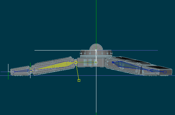
Added the project file. Mad_Cat___Food_Pad.prj Included in the project file, the rough shape/design I'm aiming for, the rectangular flipper parts (toes and heel) I'm able to do, but have not started working on for the real challenge for me is the pentagon shaped center of the foot that I've been unable to bevel correctly. Two test bevel attempts added, but I don't seem to be able to get rid of the curve, with out tweaking the bias handles I had to remake the pentagons I was working on last night, it didn't look like I saved the project progress, must have been a rage quit moment as my beveled edges test didn't work. I don't have Adobe Illustrator, so the AI wizard I've no use for. Unless there are other open source programs that can create and save in the required plugin format the AI needs to work with.
-
Currently at work, will add the project file when I get home, for I believe getting a good screenshot with the (minor) flat surface flaws (the curve) is hard to get a picture off.
-
I've done plenty of cubes or other 90 degree shaped corners and beveled them, but when dealing with shapes that don't have those corners, I'm lost. The plugin called zevel has it's use, but it's far from perfect and has it's limitations. I'm currently trying to do some trial n error bevel tests on a pentagon, but am struggling with my patch work, even tho I can get the corners better looking the surface that should be flat has a curve and there are other patch/curve problems. Did a quick search, but ik keep running in to cube bevel tutorials. These I can do, but a pentagon or octagon I'm unable to get looking good. Are there any guides that explain how to bevel corners and patch work with more details?
-
How some of those tools are right under your nose, thanks Fucher I needed that little push.
-
How do you model perfect angles/shapes. I know I can create a pentagon or octagon with the lathe tool very easy. Pentagon 5 cp's or octagon 8cp's lathe and then peak those points. Free hand guess work I don't consider to be accurate. So how do I measure/set a perfect angle manually?
-
At first I tried using a hook, but the hooks looses the smooth curve the patch had, creating a nasty border along the spline where it was hooked to. I don't believe a hook would have been a valid option to go with. BINGO! Got it to work! The problem was with a dead end spline. Got my 5 point patch problems now fixed, will do some testing later to see what is and what isn't a valid 5-point patch now that I know its being picky about dead end splines.
-
I'm having some difficulties with 5 points and turning them in a 5 point patch. Either i'm doing something wrong (most likely cause) or have a problem in my model that that I'm unable to spot. From what I know, to create a 5 point spline you need 5 splines connected to one another forming a closed loop. This is a portion of a hand, or where the fingers meet the hand. 3x 5-point patches between each finger on each side of the hand. A few of those 5 point patches are not working. I got 5 points selected, but the button remains grayed out. Normally, I select the 5 points by manually click on them one by one. If the button fails to light up, I hide every thing else except for those 5 points and drag a selection box around those 5 points, frequently this works. Every now and then I simply can't get them to work. What makes an invalid 5 point patch?
-
For Example the mousePointer ist used to determine the rotationpoint or there is a static point defined before or the object pivot or the global pivot etc. Keep in mind that most programms use a global space only... A:M has a great and intuitive way doing it. See u *Fuchur* Mouse pointer, center of screen or something along these lines. The best way I can explain it, along the lines of how AM works, everything you currently have visible in your model windows, becomes automatically selected in the background to determent the camera rotation point.
-
The problem is I've worked with other 3d/CAD like programs that had the camera handle differently, even though I'm using AM longer than any other 3d/CAD program I've worked with, I don't seem to grow used to how the camera works in AM, for I keep forgetting to select a CP if I want to rotate around whats in view. Wishful thinking on my part hoping there would be a hidden trick I've not yet discovered that alter the camera handling more to my liking's