cstanton
-
Posts
179 -
Joined
-
Last visited
Content Type
Profiles
Forums
Events
Everything posted by cstanton
-
New model & a series of questions
cstanton replied to cstanton's topic in Work In Progress / Sweatbox
That's a good tip. It seems to work most of the time, but it doesn't always work on adjacent 5pt patches. The interesting thing is that, if after doing the invert/invert, the 5pt patch icon doesn't activate, you may notice that one of the 5 CPs won't be highlighted. If you select the spline in the adjacent patch connected to this CP and detach it, your target 5pt patch usually will fill in on the next try. Of course, you've just created a new problem in the adjacent patch, but it's interesting that even when invert/invert fails, it seems to highlight the problem CP. Bill, I managed to create the hex holes using a boolean cutter. I haven't had any problems--yet--of course, I've only done a very simple animation of the model. These flybys are different formats of the same clip of the skate in its current form. The model still needs work and this simple animation shows that I have a lot to learn about lighting in A:M, but it's obviously a skate and I feel pretty good about that (amazed actually.) Broadband fly-by (Windows Media, 1.14MB) Dial-up fly-by (Windows Media, 390KB) Quicktime fly-by (1.19MB) Thanks for all the help, Curtis -
New model & a series of questions
cstanton replied to cstanton's topic in Work In Progress / Sweatbox
OK, I finally got the recalcitrant, adjacent 5pt patches to fill. Still seems like Voodoo though. I'd been either shift selecting or drag selecting in all my previous attempts, but the second patch of one pair filled in when I turned off "show bias handles"(?) and then shift selected the CPs. The second 5pt patch of the other pair required more "messing around." It finally filled in when I shift selected the splines next to the CPs rather than the CPs themselves. Don't know why that worked this time, I'd tried that several times before. Unless there's a more systematic way of doing this, I'm not sure it's worth the effort. Curtis -
New model & a series of questions
cstanton replied to cstanton's topic in Work In Progress / Sweatbox
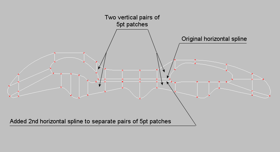
Mark, How did you get your adjacent 5pt patches to fill in? I had the same basic grouping. All the patches filled in on the first side of the model, but when I extruded the second side I couldn't get the second patch of either of the adjacent pairs to fill in. I tried all of Yves suggestions from an earlier post but nothing worked. It doesn't matter which patch of either pair I choose; the first patch of the pair always fills in, the second patch doesn't. I finally resorted to adding a second horizontal spline to separate the patch pairs. Adding to the puzzle, as I said, all the 5pt patches filled in without any problems on the first side of the model from which the second side is extruded and which looks identical. Curtis Edit: I should have mentioned that adding the 2nd horizontal line to separate the 5pt patches allows all the patches to fill in. I was just wondering if there's something I'm missing. Was I just lucky on the first side of the model, or is there a technique for filling in adjacent 5pt patches?
-
New model & a series of questions
cstanton replied to cstanton's topic in Work In Progress / Sweatbox
After looking at the other frame meshes, my big idea, because the frame was all flat surfaces, was to start with an over-sized mesh of regular squares. I laid out the profile over the mesh, connecting it to the splines of the mesh. I then removed the parts I didn't need. Because I had the previous examples in mind, I guess it's not too surprising that I ended up with a very similar result. Thanks for the help, Curtis
-
New model & a series of questions
cstanton replied to cstanton's topic in Work In Progress / Sweatbox
Interesting, thanks guys. Very clean. I'm going to use this information to try a slightly different approach. Mesh creation is turning into a strategy game. I hope it becomes less time consuming with experience. I appreciate your time and effort, Curtis -
New model & a series of questions
cstanton replied to cstanton's topic in Work In Progress / Sweatbox
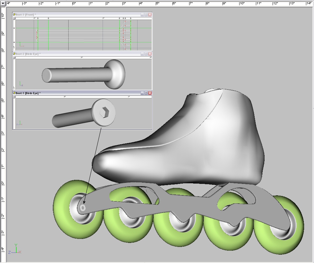
No, I'm definitely not trying to be uber-realistic. Part of the reason I'm attempting this animation is to try to simplify a complex subject. I got a little carried away with the bolt, but when it was finished I thought the hex hole was pretty cool--newbeitis I guess. If the boolean cutter thing is a problem I'll just take out the wrench hole. Thanks, Curtis -
New model & a series of questions
cstanton replied to cstanton's topic in Work In Progress / Sweatbox
Hello Rodney, Thanks for the input. I'm trying to break out of lurker mode. This is part of the project that I mentioned at the Siggraph party Curtis -
New model & a series of questions
cstanton replied to cstanton's topic in Work In Progress / Sweatbox
OK, I'm going to have to re-think the mesh. The outside surfaces are a little simpler because I didn't extend to the outside the plates that join the two legs of the frame to the boot, but there are still junctions with more than two splines. In the mean time. . . . A couple people mentioned that I might have animation problems if I just laid circles on the surface of the frame for the bolt heads and ends, so, in the interest of modeling experience, I made an axle bolt (sans threads.) My question is: Can each bolt be a boolean cutter and cut its own hole in the frame? (They're Allen bolts and the frame fills the wrench hole in the bolt if there's no hole in the frame.) I extended Tincan's internal patch removal process to create bevels on the frame by extruding the frame profile twice instead of once and shrinking the outer surfaces. It worked well enough, but not flawlessly as the bevels on the concave curves of the cut-outs were reversed, so they and the bevels on the end curves had to be tweaked by hand. Curtis
-
New model & a series of questions
cstanton replied to cstanton's topic in Work In Progress / Sweatbox
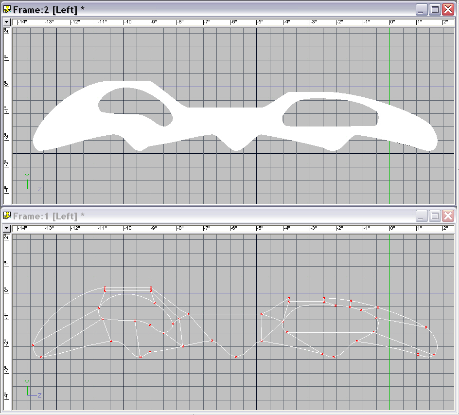
This is best profile and mesh that I've been able to come up with. There are more splines and CPs than I'd like, but there don't seem to any surface artifacts that I can see. I started over from scratch. I gave up on figuring out the principles of mesh creation. After trying to approach the mesh systematically several times I just started adding and moving CPs and adjusting biases in shaded/wire-frame mode until the artifacts were gone. The whole thing seems very fragile. Adjusting a CP just a small amount can add or remove an artifact in the narrow curved sections. I ended up changing the shape of the left cut-out, so it doesn't seem like much of a technique, but it may be time to move on. Curtis
-
New model & a series of questions
cstanton replied to cstanton's topic in Work In Progress / Sweatbox
Deleted image -
New model & a series of questions
cstanton replied to cstanton's topic in Work In Progress / Sweatbox
Deleted image, sorry, I don't know how to remove the entire post. Curtis -
New model & a series of questions
cstanton replied to cstanton's topic in Work In Progress / Sweatbox
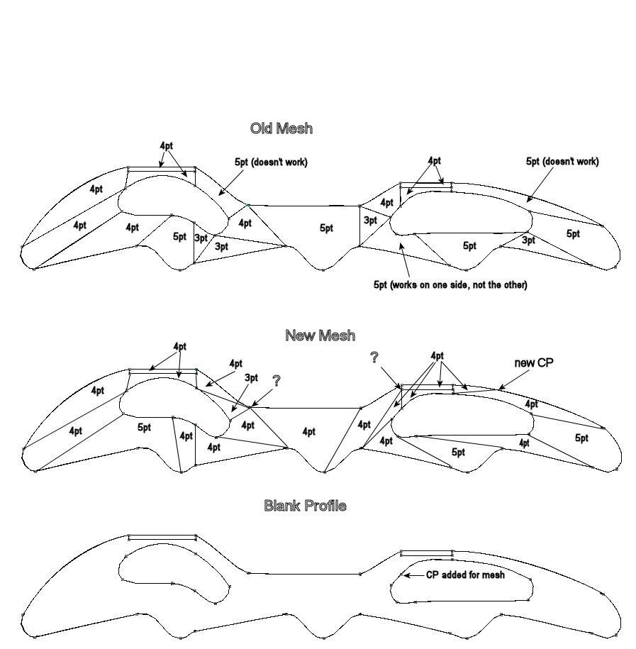
I copied the frame profile into my 2D drawing program and tried to diagram a new mesh for the frame on a layer overlay. The new mesh eliminates the 5pt meshes that weren't working. I have the feeling I still may be on the wrong track with too many splines ending at some of the junctions. I added questions marks at some of the junctions that I thought might not be good according to the Colin Freeman diagram because multiple splines are ending at the junction. Would it be better if I made two of the splines continuous at each of these junctions and peaked the CP? Thanks, Curtis Stanton
-
New model & a series of questions
cstanton replied to cstanton's topic in Work In Progress / Sweatbox
Thanks for the quick and useful replies. I've printed this thread and now that I've recovered from yesterday's all-nighter I'll try to implement the suggestions. (An inefficient way to work in the long run, but it sure is easy to get caught up in this stuff.) I just found Tincan's internal patches tutorial; that will be helpful. (Internal Patches - What to Avoid ) Ah, the rotoscopes. That was a whole 'nuther can of worms. I tried to be extremely careful when I shot the photos, but I never was able to get the different perspectives to scale so they matched exactly. I ended up winging it quite a bit when I drew the model. I tried to scale the rotos to actual size; you can see the scale of the frame in the second group of images. (The frame is 14.26" long.) Anyway, thanks for the offer. I used tga files because I wanted the alpha channel. The files are over 1MB so I posted a couple at: Left side (4.56MB) and Front (1.16MB) If you would like another arrangement or another format let me know. All the replies seem to suggest that I'm going to have to redo the patches on the frames, so even the suggestion of another strategy would be helpful. Thanks again for all the replies, Curtis Stanton -
New model & a series of questions
cstanton replied to cstanton's topic in Work In Progress / Sweatbox
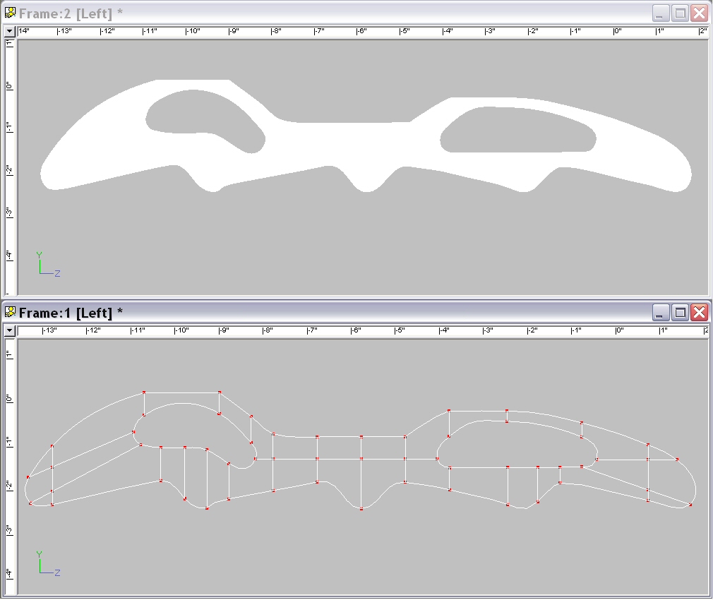
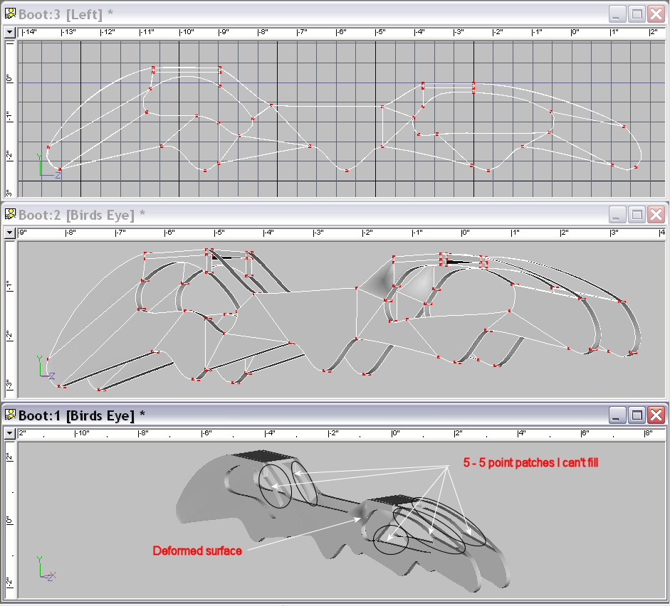
These are additional images of the frame with the unfilled five point patches, misbehaving splines and deformed surfaces. Thanks again, Curtis
-
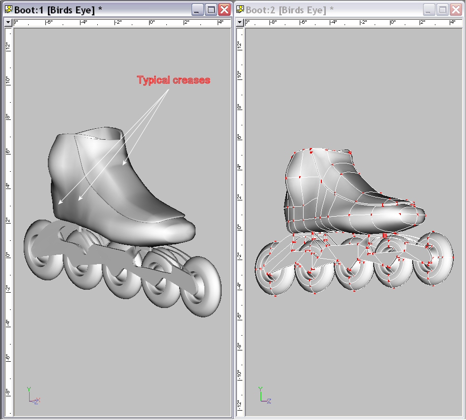
This post is more of a query than a showing of new work, but I'm going to be presumptuous and post this in the WIP rather than the New Users forum. This is a model of an inline speed skate. This is my second model, the first with curved surfaces, so I have a number of questions. I'm sure all of these questions have been asked and answered before, but I'm still looking for those answers. If anyone can point me in the right direction, I'd certainly appreciate it. 1. What is the best way to remove the creases in the model's surface? 2. Ideally, I'd like to radius the edges of the frame (the metal structure below the boot), but the short splines connecting the two profile surfaces don't have bias handles and changes to the manipulator properties value don't seem to have any effect, the changed values snap back to the original values. I created the frames by drawing the profile of the frame and then extruding the second side. Would it be better to copy the profile and then add the connecting splines? Or is there some other way to get control of these short connecting splines? Actually, none of the "interior" splines seem to have bias handles, they have bias "arms," but no handles that I can grab. Is that normal? 3. Some of these internal splines warp when I make changes to the external spines to which they are connected. Since there's no bias handles, I have to disconnect the splines and reconnect them. Often these spines straighten when I select them and re-warp when they are deselected. I've tried to re-do some of these several times--that can't be right(?). I add tails to these splines and to the connecting CPs before connecting them so they will remain independent splines, but it doesn't prevent the problem. 4. There seem to be interior four point patches created by the lateral connecting splines that are not visible and serve no purpose in the finished model. Can these be removed or avoided? 5. Would there be problems that I don't foresee at present if I add circles just touching the surface of the frame so I can apply a different material representing the flush ends of the axles? (Rather than connecting the circles to the surfaces with more splines.) 6. Five point patches are a mystery. I must be using them improperly because they seem inconsistent. Sometimes they fill in properly on the first try. Sometimes a patch will fill in after repeated failed attempts. And sometimes they don't fill in at all. Thanks, Curtis Stanton
-
For those of us stuck in the dial-up time warp: How big are these files? Thanks, Curtis