


R Reynolds
-
Posts
176 -
Joined
-
Last visited
-
Days Won
47
Content Type
Profiles
Forums
Events
Posts posted by R Reynolds
-
-
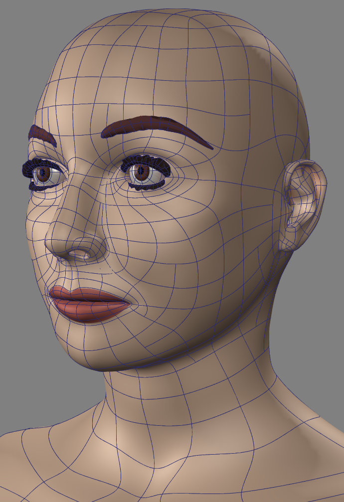
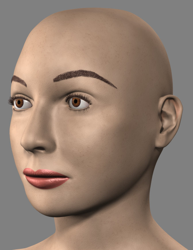
Each eyebrow uses four hand drawn "hair" images. The first is applied as a colour and subtle bump decal on her skin. The other three are used as transparency decals on three separate patch layers, one on top of the next to suggest some thickness. The upper eyelashes use two layers of transparency decals while the lower lashes are only a single layer. The eyelash decals started life as images from on-line stores selling false lashes.
-
 2
2
-
-
This was the hardest model I've ever attempted. For mechanical models it's relatively easy to find front, side and top reference images, not so much for 1940's movie actresses. Every time I looked at a different 3/4 view of Ann Sheridan with dramatic lighting and did a test render, I found another CP that needed a small relocation or a spline layout that needed a rethink. I can see why 3D scanning of an actor's face is so appealing for a digital replacement. I still don't think the likeness is convincing but I'm sending her to Hair & Makeup anyway! (Maybe I'll say I'm modeling Ann Sheridan's stand-in. 😄 )
-
 2
2
-
-
Thanks very much, Robert. This is all entirely new to me so it looks like it's time to climb that learning curve.
-
Quote
...SSS only works in renders to file
SSS is not calculated with a progressive screen render. But compare the attached, render to file image with the previous final screen render and they appear to have very similar results.
Quote...do the AO as a separate pass and composite it
You say that as though there is an SSS buffer that can be rendered separately. I started browsing the SSS sub-forum and found that this has been an issue since at least 2008 and in this https://forums.hash.com/topic/33040-rendering-sss-separately/ thread almost exactly 15 years ago you wrote;
QuoteI don't think A:M's OpenEXR render includes a separate AO buffer. You'd have to make one manually, which clever people do.
So I guess I'll have to be more clever 😄.
-
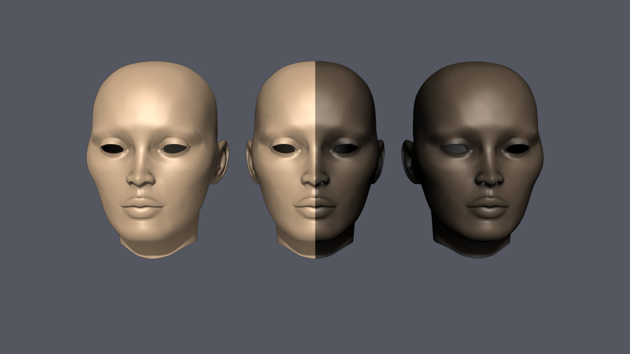
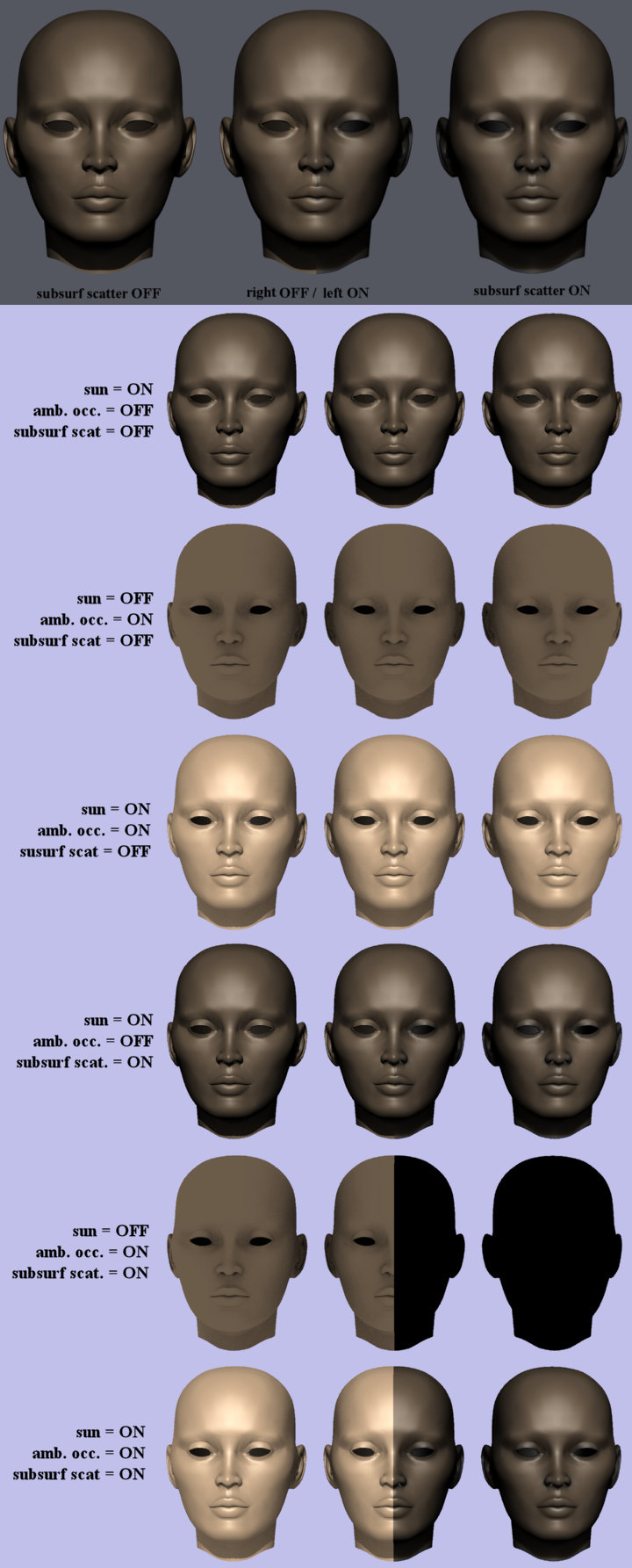
Shown are three copies of the head of the Jungle Queen. Each head uses single attribute "skin" materials. The leftmost head material has subsurface scattering turned OFF while it's turned ON in the rightmost head. The centre head has subsurf. scat. turned OFF on it's right side while it's turned ON on it's left side. These three models are arranged in a chor that uses a single "sun" style light source and the global color (256, 256, 256) for ambient occlusion.
With subsurf. scat. turned off in the camera, all three heads are screen rendered as expected with just sun, just ambient or both illuminating it. When subsurf. scat. is enabled in the camera and the only illumination is the sun, the screen render is as expected. Turning on ambient occlusion in the chor and the screen render is not what I expected.

Results are identical in V19.0p and v19.5a.
-
Thanks, Gerald. Unfortunately, after updating the drivers I still have the same issue.
-
For a very long time, one of the nice tools in A:M is being able to constrain cp motion along an axis during a rotate; see embedded project.
This is a top view of two tubes whose axes are parallel to the Z axis. Open this project in v19p (or any version going back to the last century) and select the central circular 4pt. spline of the green tube.
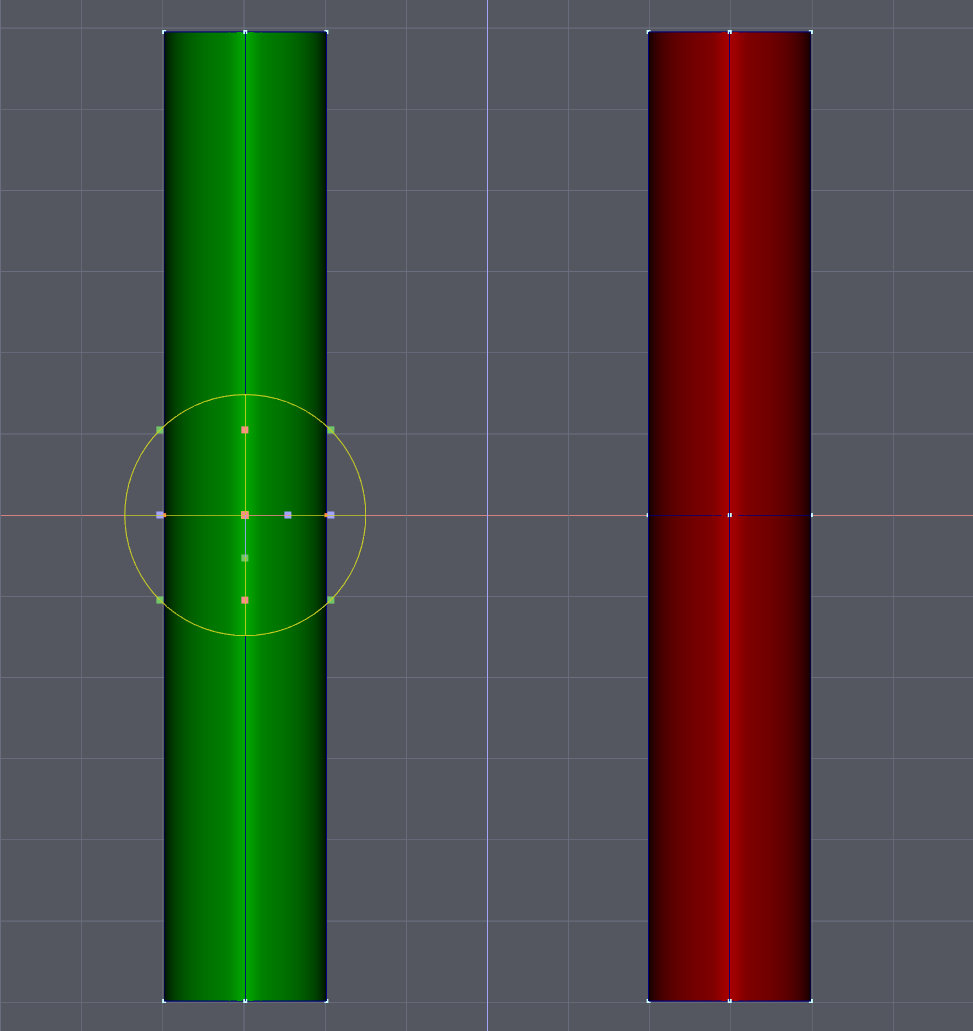
Select the Rotation tool and rotate the tool 45 deg. counterclockwise while holding down the 3 key.
The spline rotates but the movement of the cp's are constrained to only move along the Z axis.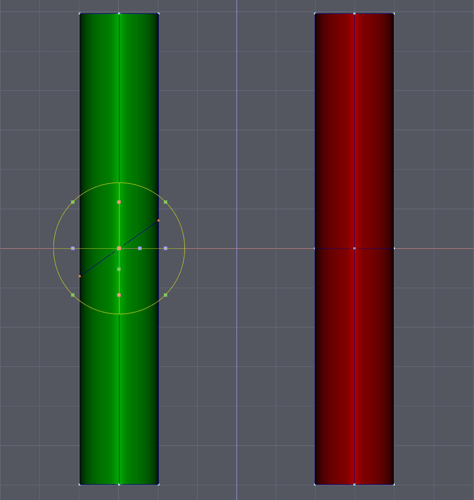
Open this project in v19.5a and select the central circular 4 pt. spline of the red tube.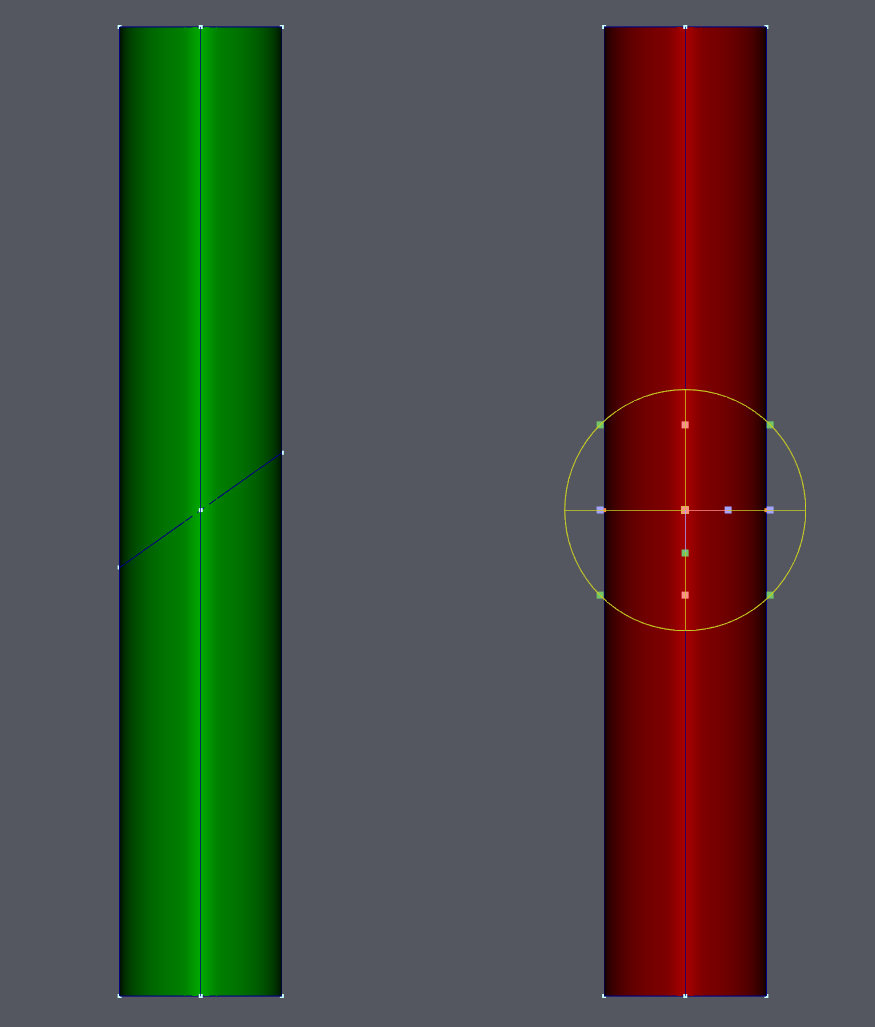
Select the Rotation tool and rotate the tool 45 deg. counterclockwise while holding down the 3 key.
The entire spline moves with no axis constraint, the way it would if you weren't holding down the 3 key.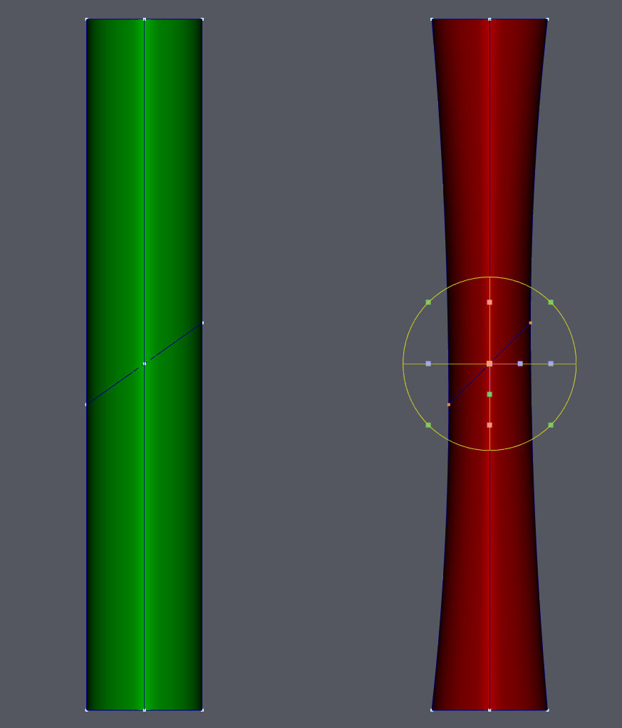
This is also true for the X & Y axis.
-
Right you are Robert! Thanks. I'd long forgotten about that option. After turning it on I didn't notice that the render was noticeably longer, so it it stays ON by default. Sorry about the missing images, they were a holdover from my original test for believable female eye-lashes which started this whole thread.
-
This issue may not be fixable if it's an unavoidable side effect of how AO works but I'll submit it anyway.
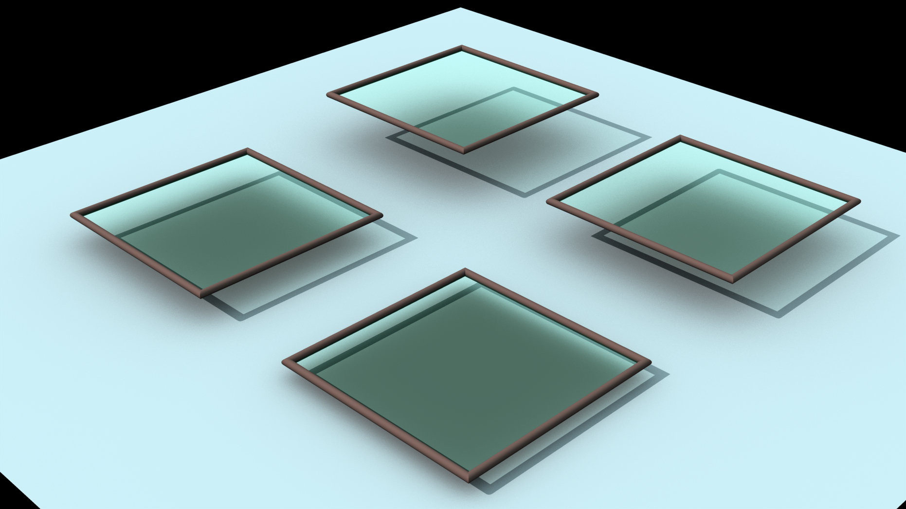
Here is a prog. render of the test model illuminated by a sun type light source. The model is a flat grey surface above which hovers four glass windows. Each window model (7 in. x 7 in.; 17.8 x 17.8 cm) is 4x4 patches surrounded by a tubular frame. The greenish glass has a 90% transparency. Each window is floating a different distance above the grey surface ranging from 2 in (5.1 cm) to 1/2 in. (1.3 cm).
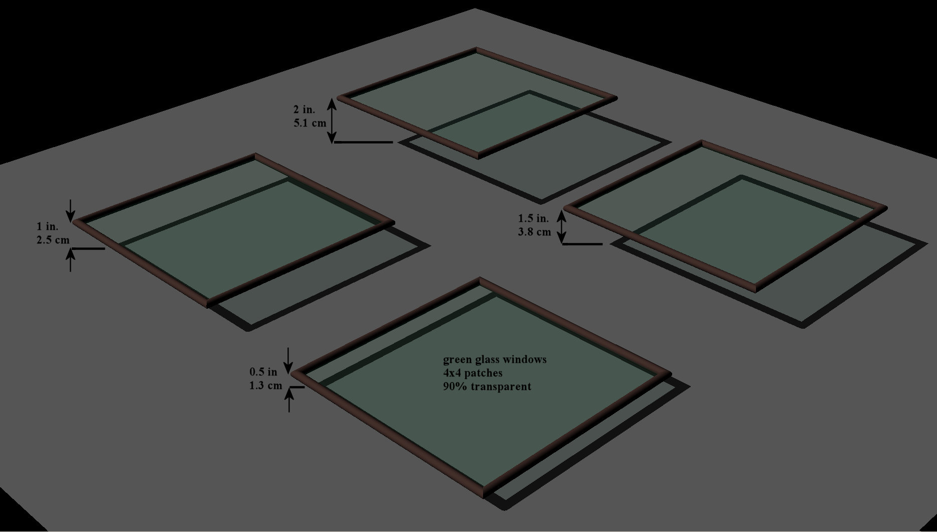
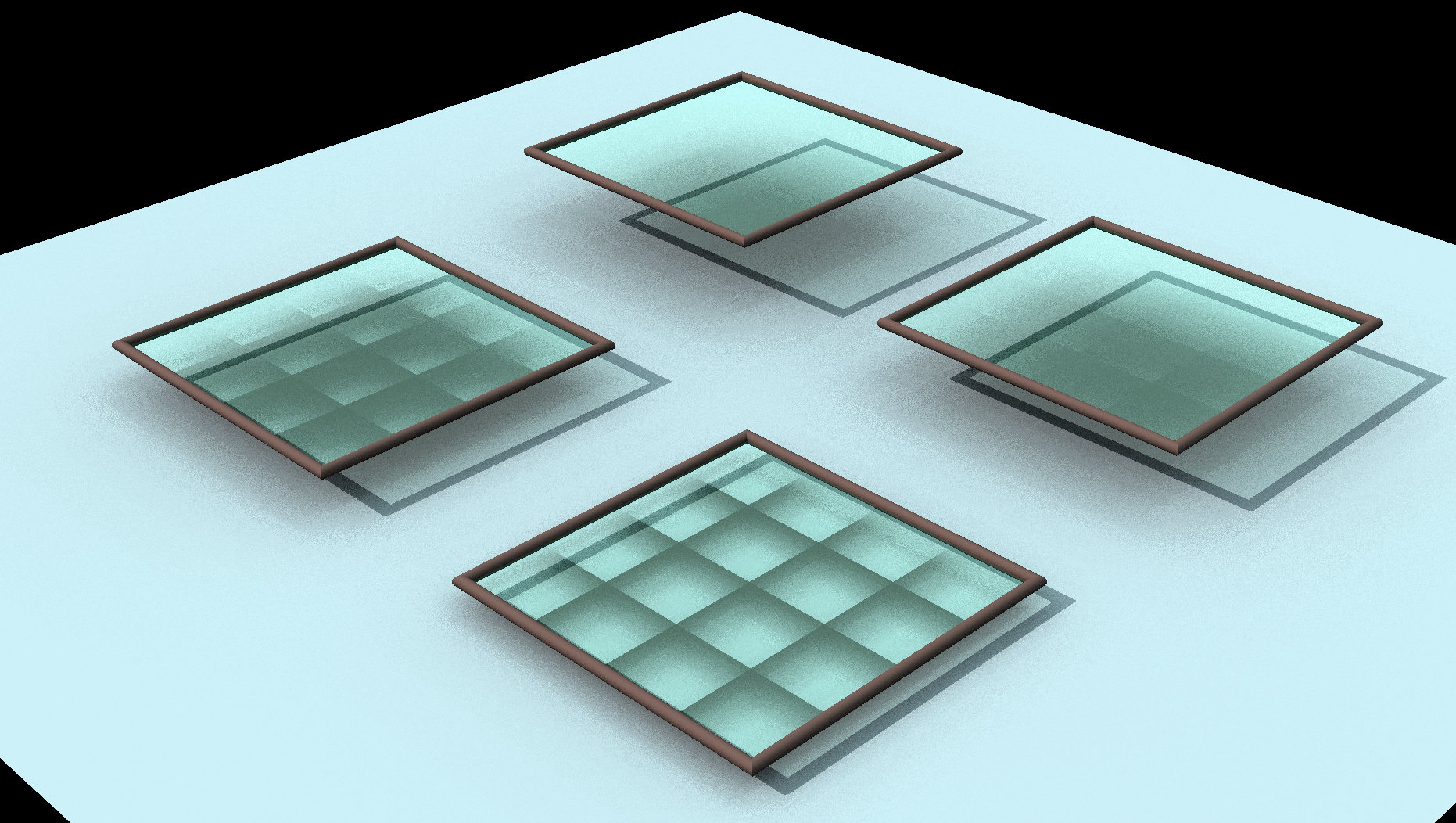
This is a final render(9 passes) of the model after you turn on AO = 100% with a sky blue global colour. Notice that the ambient light is still being partially blocked by the almost transparent glass and the shadow density increases as the glass gets closer to the surface. If you reduce the transparency of the glass, the density of its ambient shadow increases so clearly AO is sensitive to the surface transparency. But even at 100% transparent the glass still has a noticeable ambient shadow when its very close to another surface.
Even stranger is a progressive screen render with AO on.
This also happens in v19p. Embedded project is attached.
-
I've started building my next actor and have decided that she's going to have believable ears. A number of human A:M models have been made available over the years.

Jim Talbot made a low patch count ear with Wonder Woman because they were hidden by her hair. For the same reason the ears on Den Beauvais' Lambrina are only good at a distance. Jim Talbot got closer with Lady Goodbody and the Jungle Queen with ears that were incorporated into the skull mesh but they still don't stand up to arm's length scrutiny. I tried my best on the business man with a hi-res normal view of an ear as a rotoscope but his ears are only sort of convincing in a normal view because I couldn't get the depth right.
So I purchased a ridiculously hi-res poly model of a female head and used one of its ears as a template.

At left is shown the rear, side and front view of the template. The next image shows a rendering of how well I was able to match the spline model (in tan) with the poly template (in grey). The only place where my model deviates from the poly model is that my ear has a real ear canal. The next image is a rendering of the attached ear model which includes a chunk of surrounding skull with all the connecting splines. The last image is a normal view of the model with Average Normals ON and Normal Weight = 50.
-
1
-
-
I've left a large poly model running for days and could never get beyond 30%.
I've had success with installing Blender and reading just enough of the on-line manuals to reduce poly count and in some cases convert triangle polygons to rectangles (or quads in their jargon).
The foot on the left is the imported prop and one the right is the .mdl converted from a reduced poly version.
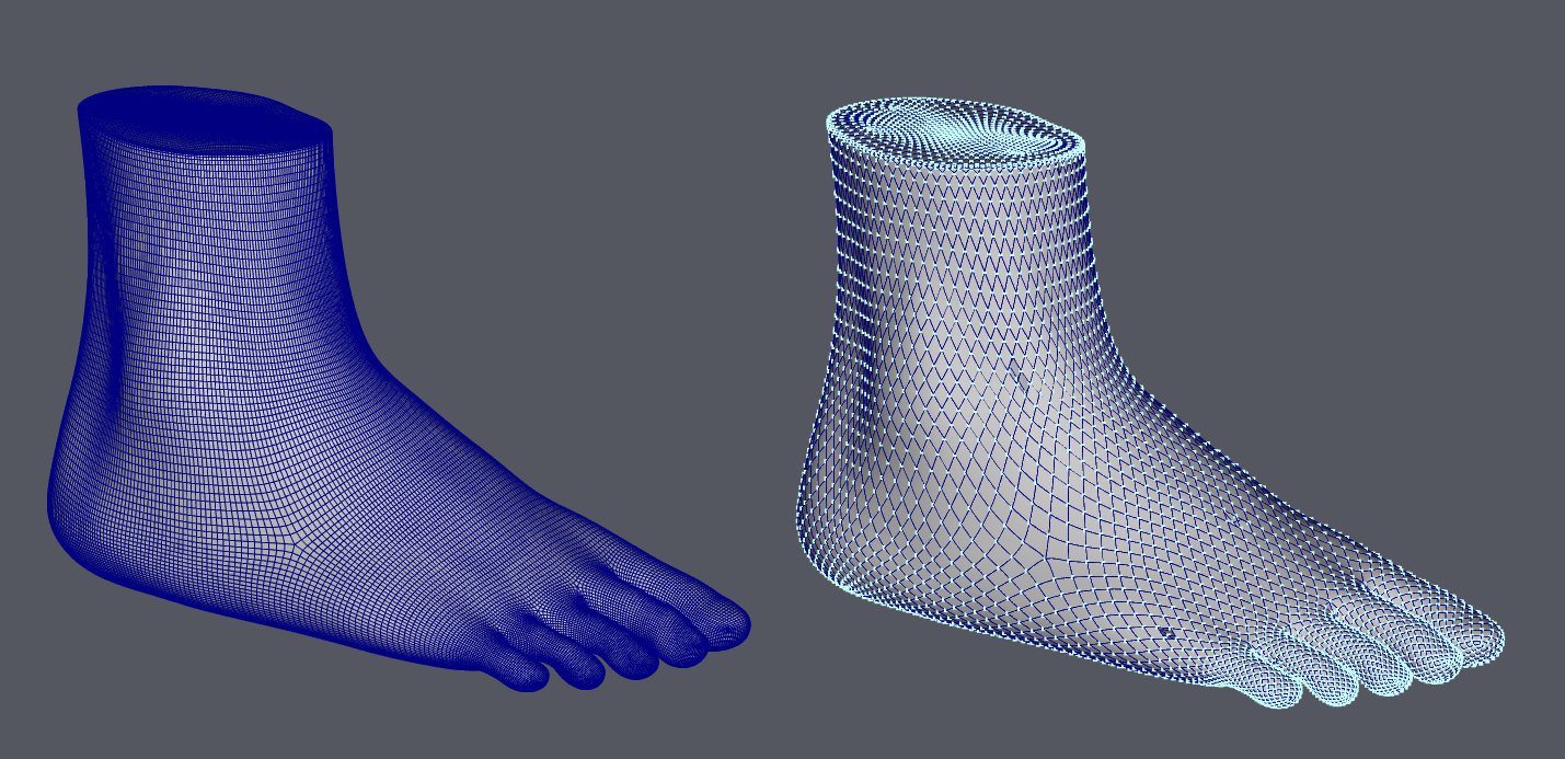
I find there's an advantage to having your template model in .mdl format in that I can easily isolate an area and eliminate the "snap to surface" choosing the wrong side.
-
1
-
-
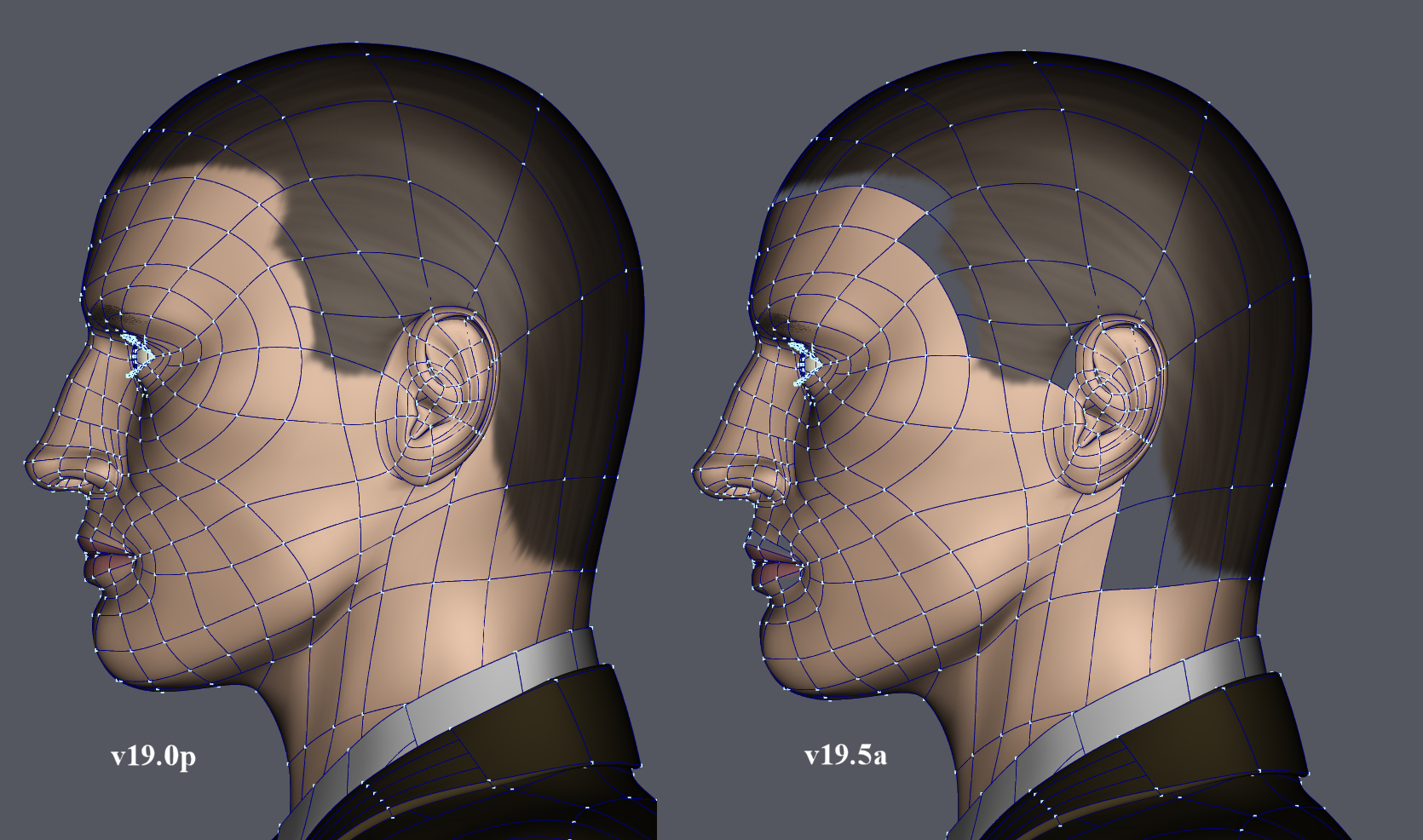
Progressive screen renders have issues with most but not all hooks as the weights of averaged normals increases from 0.
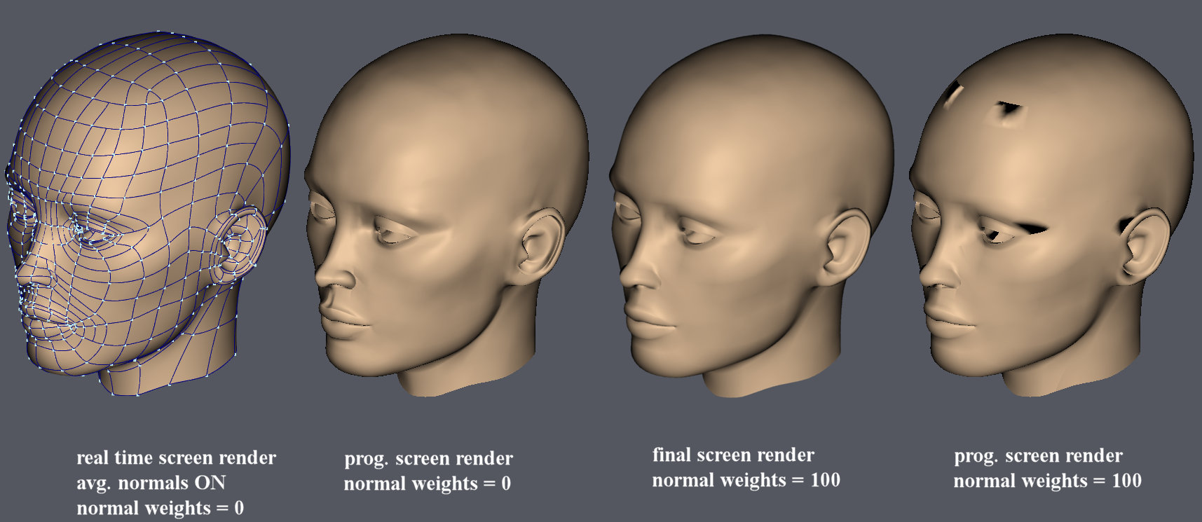
All normals are aimed in the outward direction. The hooks on the rear skull, the nose and near the mouth don't seem to cause problems.
-
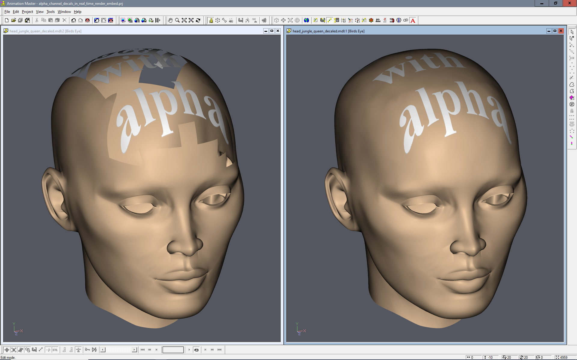
Use v19.5a to open the attached embedded project of the jungle queen's head which has been decaled with text with an alpha channel. The image on the left shows a real time render of the head. Progressive renders produce the more correct image on the right.
-
Sorry about that, I forgot to turn on the "show advanced properties" option. This isn't the first time I've done that. ☹️
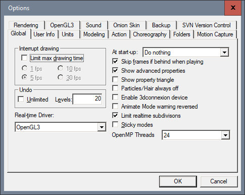
Is this data stored in a file that can be copied to the v19.5 folder so I get all the v19p options that I've taken for granted?
-
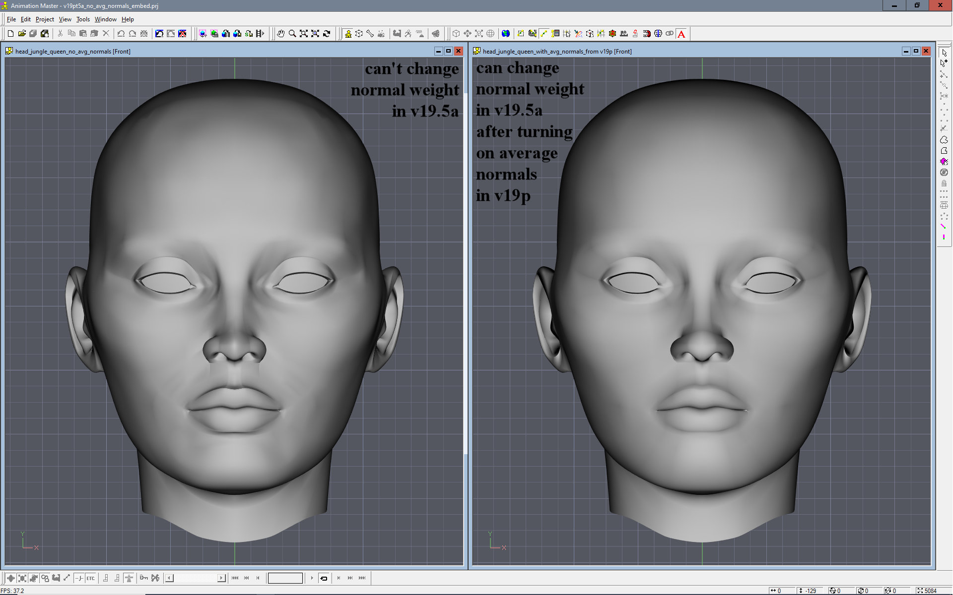
Open the attached project in v19.5a. It has two versions of the same model.
On the left in head_jungle_queen_v19pt5a_no_avg_normals.mdl, you can not change the normal weight of averaged normals because there is no "Average Normals" YES/NO switch in v19.5a. You can try changing the value of "Normal Weight" but it has no effect. On the right in head_jungle_queen_with_avg_normals_from v19p.mdl you can change the normal weight of averaged normals because this model was opened first in v19p and the "Average Normals" switch was set to YES.
-
Sorry, Robert, I just saw this now. I'll get on it.
-
Here is a comparison of a real time screen render of the same model. v19.5a appears to have an issue with alpha channels in decals, rendering the patches as clear. Progressive renders are correct in both versions.
-
Thanks for the video, Robert. It confirms what had made sense to me from a kinematic links standpoint. The highest points of the pelvis are when the legs are vertical beneath it. Building a walk cycle became more straight forward once I worked out the motions of the pelvis.
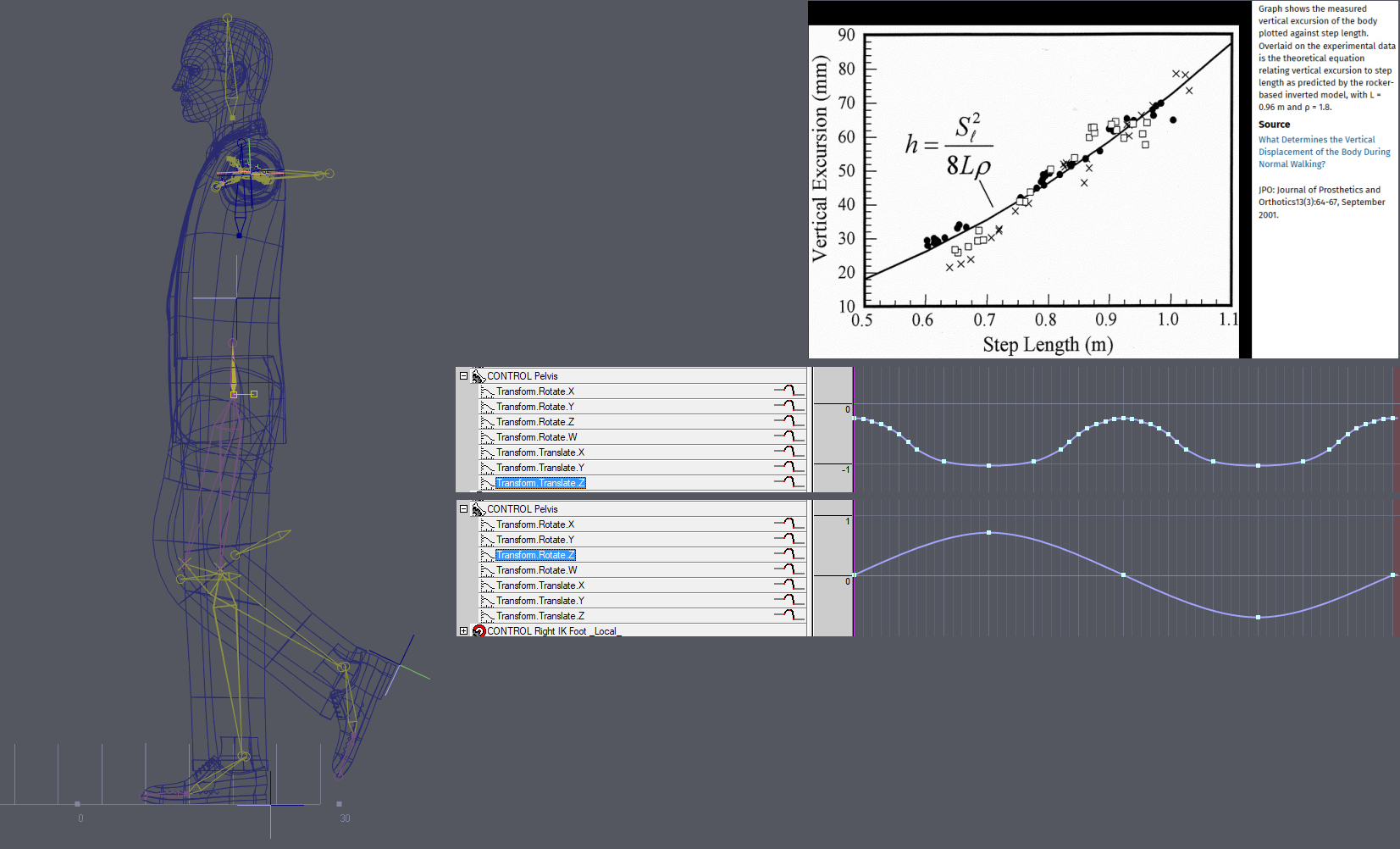
I chose pelvis motion limits that were on the low side since I was going for a more subtle stroll as opposed to your "walking with purpose" video. I assume that once I work out all the cycle details, I can always scale the motions up.
-
Quote
Did this ever get made an AM bug Report?
Not to my knowledge.
QuoteHave any newer card drivers come out since this thread?
In the past, AMD updated drivers automatically and I haven't seen a new one since this issue started last fall.
QuoteNarrate your actions as you go through the motions and note the problem.
Please review the attached video and let me know if I've missed anything.
-
It may only be the legs but it's a good start.
-
I see v19.5a still has this issue. Should I run a video capture of what I'm talking about as an example for Steffen?
-
Do I still need to run v19.5a in Compatibility mode?
-
The attached embedded project contains a four patch, vertical plane. The left side has a material that uses AM_Dirt while the right side uses a material with AM_Turbulent. When the attached .atx and .trb files are in the correct folders, AM v19.0p opens without incident as well as the attached project. Render the plane and you get this
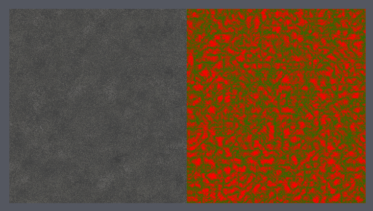
However with the same files in the correct folders for v19.5, as it opens, AM brings up the previously noted error concerning the .atx file. Click OK and v19.5 opens. Opening the attached project and you get this error
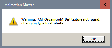
Click OK and the project opens. Render the plane and you get this
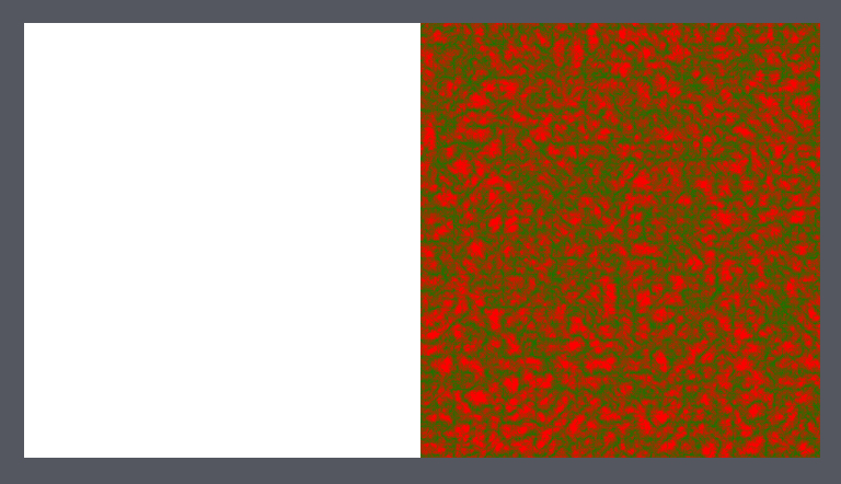
EAM_material_surface_embed.prj EnhanceAM_Dirt_64.atx EnhanceAM_TurbulentCombiner_64.trb
-
Quote
Have you gone into the folder V19.5\Textures\ to see if it's there?
Yes, all 40 files are in that folder.
QuoteIf the v 19 version of the plugin doesn't work in v19.5 then it would have to be recompiled by the programmer.
I really do hope you're wrong. I use those ATX files A LOT and EnhanceAM_Dirt_64.atx almost everywhere. As you can see from the file name, it was recompiled by the programmer to 64 bit back when we made that upgrade. I don't see why the TRB files, which also have the _64 suffix, should work but the ATX files do not.
My first female head
in Work In Progress / Sweatbox
Posted
Yeah, I tried that but that five point patch to the left of your first X (which then extended to your second X) started to do that "hey your stretching the 5 point algorithm too far" thing; acceptable with lots of surface texture, not so much on a cheek. My philosophy was to keep five pointers as small and symmetrical as possible. If the price for that is eight extra patches, so be it.