


pleavens
-
Posts
597 -
Joined
-
Last visited
Content Type
Profiles
Forums
Events
Posts posted by pleavens
-
-
Have you tried multiple specular only lights, one for each specular highlight angle. Or does the toon renderer not use the additional lighting?
Phil
-
If the decal "y" number is keyable, you should be able to make the change happen in the pose itself. (I assume you used a pose to drive the vertical scale)
If not, you could make a sequence of images and then drive the sequence frame with the pose.
Phil
-
I used Steffen Gross's "spring" plugin to make the threads for this screw.
http://www.sgross.com/plugins/plugin1/index_e.html#Feder

Seemed to work ok.
Phil
-
Try using at least two different types of force objects.
Example of using a fan and a vortex combined.
Phil
-
Right click on the force object and add your choice of turbulence.
-
Is there any way to see what angles have keyframes in them on a SmartSkin any more?
"Next" and "previous" keyframe buttons will jump the bone to the keyed rotation.
Phil
-
Sooo, is that the project attached to your post?
Yes.
-
Aah, this is going to seem like a lot of work but it will save you a ton of grief in the end.
1. Position the default bone at <start x=0, y=0, z=0> and <end x=0, y=0, z=1>
2. Attach the body core to a bone.
3. Translate the entire model using the "body" bone in bones mode to center it in "x" and place the "feet" at 0 "y"
4. Delete the entire "drivers" folder that has unused settings for the materials applied.
5. Delete all the existing smart skins that use "muscle mode" to rotate the gears. Due to the linear interpolation method of cps that are not controlled by a bone this method of doing the "gears" animation will not work.
6. Add bones for each gear.
7. Set up the rotational relationships using the gear bones. you can do this using smartskin to drive it directly in your existing FK setup.
I'll post your model in a bit with this type of system applied to the right side of the jaw for you to work from. And most of the other stuff taken care of as well.
Phil
-
The models not embedded in the project.
-
Umm the ZIP link seems to be broken!
Should be good now. Thanks for letting me know.
Phil
-
http://www.hash.com/forums/index.php?showt...ndpost&p=106395
Edited and Zipped!
Yeash, should not have posted before edit, I just got tired of seeing folks making a massive Mountain out of an awesome Smart Skin molehill!
Phil
-
When I get home, I'll zip it up and provide a link.
Sorry.
Phil
-
EDIT!!! Massive and desperately needed edits done. Hopefully this is MUCH easier to understand now!
Click to download ZIPPED file. 4.3 megs
EDIT: LINK FIXED
Phil Leavens
-
No... but I looked at the BB Code (by quoting your post) and it looks like you have three slashes after http: instead of two.
Zach! that was it. I didn't catch it as Firefox and Explorer on both my Linux and Windose box's displayed it fine. I'll be more careful in the future.
Fixed now.
http://www.hash.com/forums/index.php?showt...ndpost&p=104620
Phil
-
Um... was there supposed be an image below that? I got a question mark (Safari equivalent of a red X).
http://www.hash.com/forums/index.php?showt...ndpost&p=104620
Zach, is it showing up now?
Phil
-
Glad to see the video, I sent in a friend of mine to check and make sure they were ok.

-
You have to be specific in the keys you are setting. So far you have told the LAYER to repeat any action applied to it. As the layer can only be translated, scaled, and rotated, you will get the result you have.
The item you wish to have repeat is the "Image Frame" property of the layer.

-
What you are seeing is a result of your realtime subdivision setting being too low to define the patch correctly.
If your system can handle it you can raise the level (hit page up to increase, page down to decrease) and the realtime view will look more like the final render.
This is NOT REQUIRED in any way, but it will give you a better "look" at what you are working on.
Phil
-
but how do you set it so that it starts at (say) 33%, goes around to 100%, back to 0% and then up to 33% again? (i.e. starts and ends at the same point on the path, but not at the start/end of the spline.)
Dunno...
Here's a sample project that I think will answer your question.
Phil
-
Spent some more time today trying techniques for compositing shaded dynamic hair. Here's the result so far.
New shaded composited hair movie.
Total render time on an Athlon 1400 (hair pass and composite pass) was about an hour and a half!
Phil
-
The whole blurring and fuzziness works great - how did you do it?
All the odd distortions are caused by a refractive animated transparent grid in front of the camera. I also used the stock "old film" post effect.
Phil
-
-
-
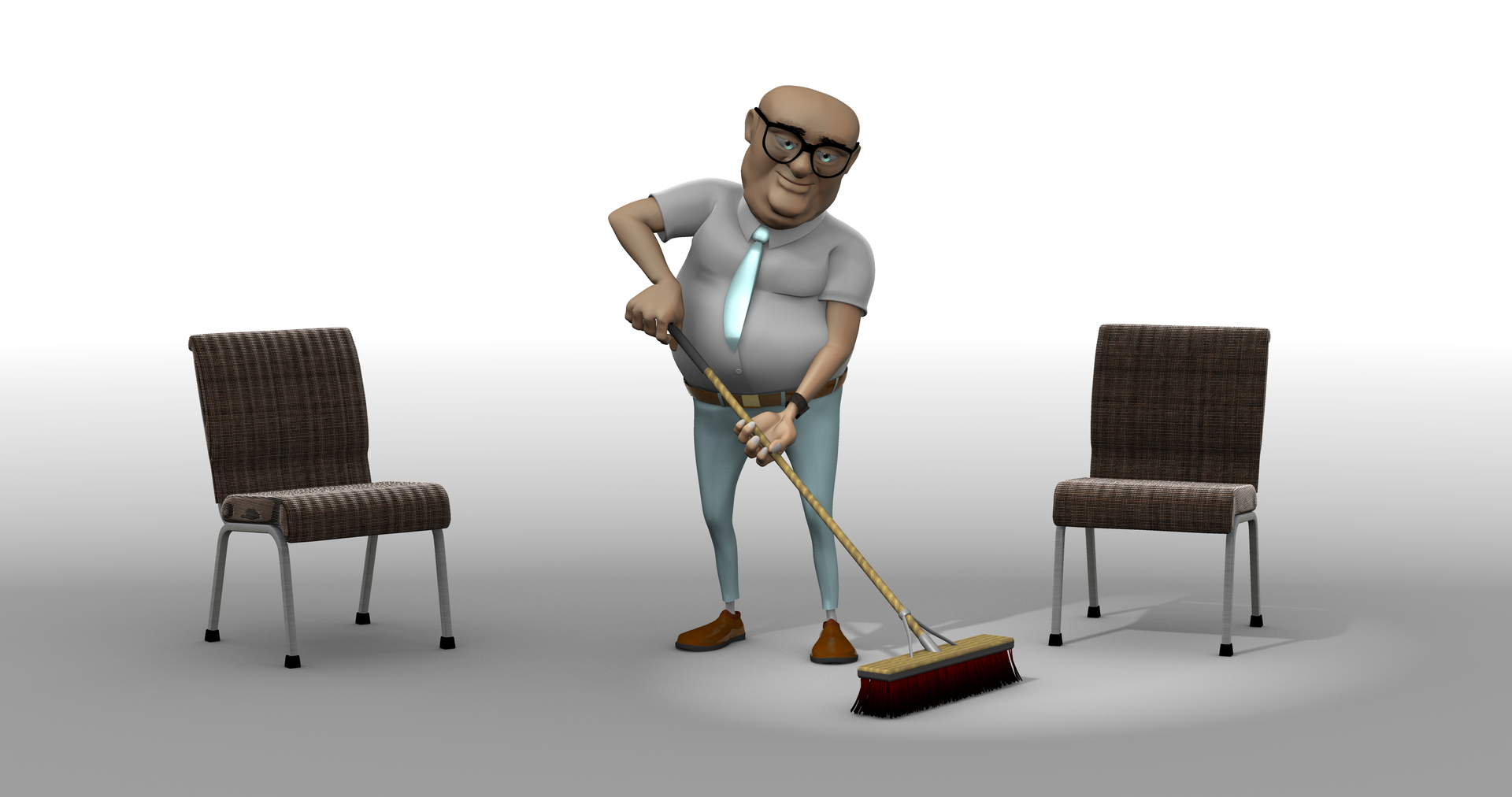
Here he (it?) is with a test texture applied.

New model & a series of questions
in Work In Progress / Sweatbox
Posted
Someone suggested inverting the 5 point selection and then re-inverting to select ("." x2)
Doing so has worked well for me.
Phil