


cstanton
-
Posts
179 -
Joined
-
Last visited
Content Type
Profiles
Forums
Events
Posts posted by cstanton
-
-
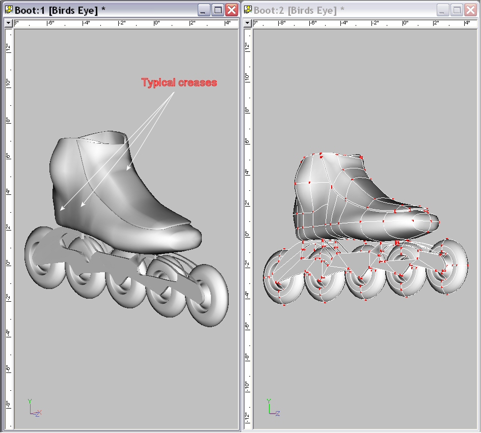
This post is more of a query than a showing of new work, but I'm going to be presumptuous and post this in the WIP rather than the New Users forum. This is a model of an inline speed skate. This is my second model, the first with curved surfaces, so I have a number of questions. I'm sure all of these questions have been asked and answered before, but I'm still looking for those answers. If anyone can point me in the right direction, I'd certainly appreciate it.
1. What is the best way to remove the creases in the model's surface?
2. Ideally, I'd like to radius the edges of the frame (the metal structure below the boot), but the short splines connecting the two profile surfaces don't have bias handles and changes to the manipulator properties value don't seem to have any effect, the changed values snap back to the original values. I created the frames by drawing the profile of the frame and then extruding the second side. Would it be better to copy the profile and then add the connecting splines? Or is there some other way to get control of these short connecting splines? Actually, none of the "interior" splines seem to have bias handles, they have bias "arms," but no handles that I can grab. Is that normal?
3. Some of these internal splines warp when I make changes to the external spines to which they are connected. Since there's no bias handles, I have to disconnect the splines and reconnect them. Often these spines straighten when I select them and re-warp when they are deselected. I've tried to re-do some of these several times--that can't be right(?). I add tails to these splines and to the connecting CPs before connecting them so they will remain independent splines, but it doesn't prevent the problem.
4. There seem to be interior four point patches created by the lateral connecting splines that are not visible and serve no purpose in the finished model. Can these be removed or avoided?
5. Would there be problems that I don't foresee at present if I add circles just touching the surface of the frame so I can apply a different material representing the flush ends of the axles? (Rather than connecting the circles to the surfaces with more splines.)
6. Five point patches are a mystery. I must be using them improperly because they seem inconsistent. Sometimes they fill in properly on the first try. Sometimes a patch will fill in after repeated failed attempts. And sometimes they don't fill in at all.
Thanks,
Curtis Stanton
-
For those of us stuck in the dial-up time warp: How big are these files?
Thanks,
Curtis
New model & a series of questions
in Work In Progress / Sweatbox
Posted
These are additional images of the frame with the unfilled five point patches, misbehaving splines and deformed surfaces.
Thanks again,
Curtis