

LenseOnLife
-
Posts
45 -
Joined
-
Last visited
Content Type
Profiles
Forums
Events
Posts posted by LenseOnLife
-
-
Hi,
Thanks for that feedback - it looked so easy (till I was let loose)!
Unfortunately I seem to have screwed up everything

I made up sub-directories and shortcuts to the various materials - every looked brilliant - just what the doctor ordered. Then I noticed that I had mistakenly stored everything in the 'Hash Library1' which is not what I had intended to do. It was at that stage that I noticed the 'My Library' option and thought to myself - that would be a safer place to deposit all the shortcuts. It had a load of empty folders, and to keep everything clean, I deleted them all in preparation to inserting my own ones BUT when I then went back to the 'Hash Library1' it is now empty!!
1. Is there any way of getting back the Hash Library1?
2. Is it possible to make up a new library with just my own materials in it that I can store in my own location rather than under the V.18 folder i.e. totally independent of the Hash Libraries?
Guess I'll get there .... eventually
Oliver
-
Hi,
Am wondering if it is possible to have a 'personal library of materials'. I see in the tools->OPtions->folders it is possible to add extra path for A:M to search for additional LBR files. I have a number of materials files and am wondering how can I put them into a LBR file so that A:M will recognise them.
Have searched the internet for a utility without any success.
Any ideas - or am I simply barking up the wrong tree and there is an easier way that I've missed?
Thanks,
Oliver
-
Too embarrassed to admit how many days I've been searching for that wee dropdown

Thanks
Onwards and upwards
Thanks,

-
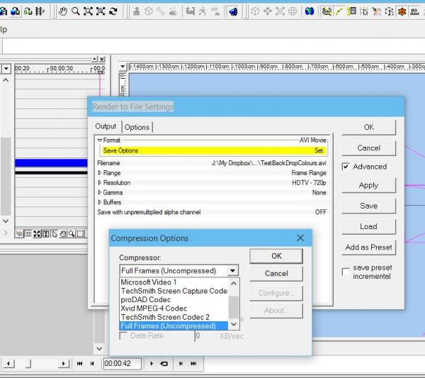
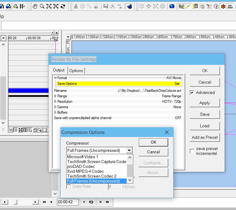
Having explored it a bit more I see that I need to render to an 'Image Sequence' - that is what I don't seem to be able to find.
I'm using A:M V18
When I 'Render to File' the format is 'avi' and I can't see how to change that to a sequence rather than an avi (see attached screen grab'. Have checked the Tools -> Options -> Rendering but that is set to AVI as well and I can't find any reference to 'Image Sequence'
Oliver
-
Hi,
I must be missing something VERY basic. How do I create a rendered version of a frame of scene/choreography?
I have a choreography, I don't want to render the entire choreography just a single rendered frame from within the choreography
Make sense?
Oliver
-
Good Morning All from a REALLY wet and windy mountain in SW Ireland,
As I mentioned at the outset, I am just experimenting now with AM and trying to become proficient and understand what the limitations are so as to avoid those dark corners that tend to catch me unawares. It just takes time to get things straight and understand the AM way of doing things. Been using MovieStorm which has a very shallow learning curve and, while AM takes more learning, it does seem to have much greater facilities and should be worth the effort in sticking to the learning process.
So, thanks for all that great background information.
Cheers,
Oliver
-
Hi,
I'm inclined to agree that it might be something to do with the maths but can't quite work out what.
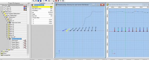
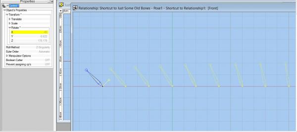
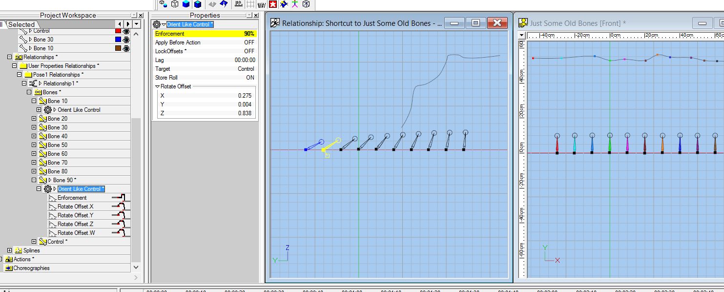
I set up another model with bones - the left hand is the control bone and all others are oriented like it but enforced at 90%, 80% .... down to 10%
Results are interesting - there is definitely a change in behaviour when we go below 50% and at the 180 degrees the 50% bone switches plane by 90 degrees - which leads me to believe that using 50% or lower could be problematic.
Rodney - what exactly did you mean by making sure that the enforcement is not set to hold. How did you get that menu showing?
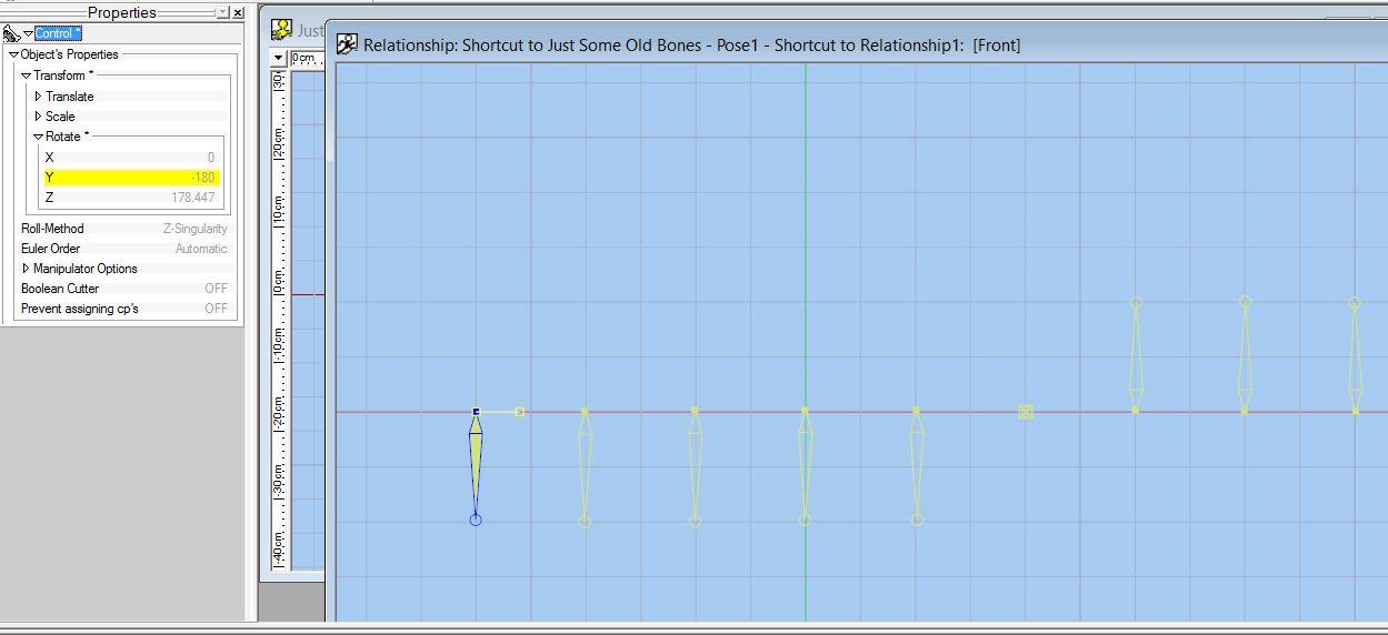
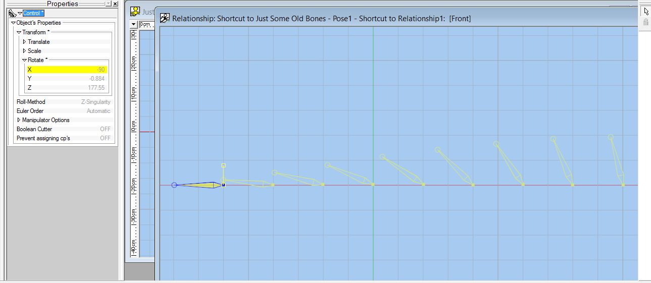
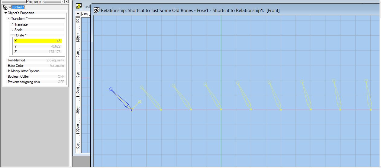
And here are the rotations in 45 degree increments


This is more of a curiosity at this stage as I don't have to use a constraint below 50% - but would like to know of limitations now rather than later when I am using them 'for real'.
cheers,
Oliver

-
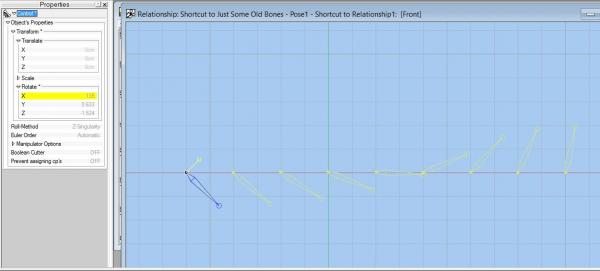
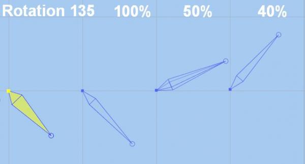
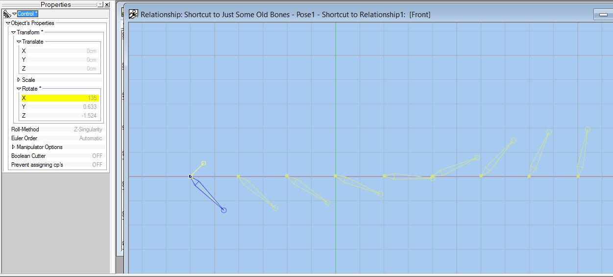
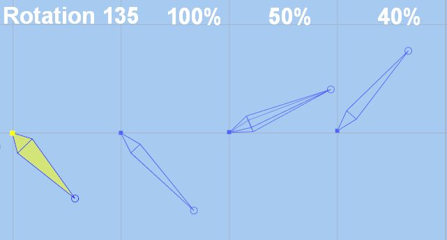
Hi, Just noticed a mistake in my explanation and images.
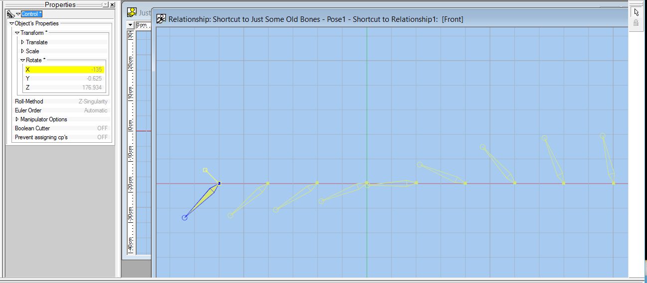
For the 40% enforcement at 135 degrees rotation is where it stops following the control bone in a positive direction and STARTS reversing.
The following image shows the relative rotations near 180 degrees where you can see that the 40% enforcement has almost returned to its zero position while the 50% is almost at 90 degrees.
Regards,
Oliver
-
Hi,
I've been working my way slowly through Barry's great Video Tutorials and then trying them out in practice and have come across something that I don't understand. It is to do with constraints where the enforecement is less than 50%
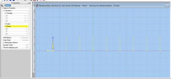
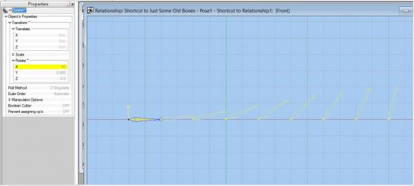
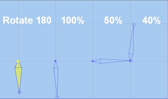
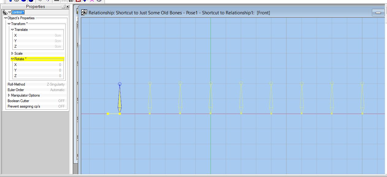
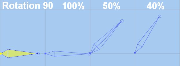
Rotate-00 shows the 'home position'. All 4 bones are pointing straight up. The 'control bone' is on the left and the other three bones are all constrained to orient the same as the control bone as follows:
Going from left to right, the first bone is enforced with 100%, the next bone is enforced 50% and the last bone on the right is enforced by 40%
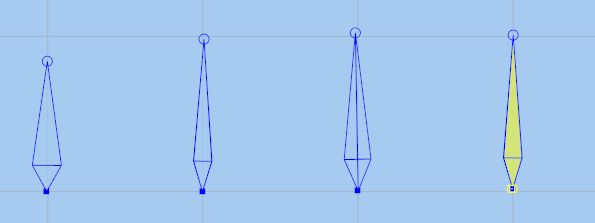
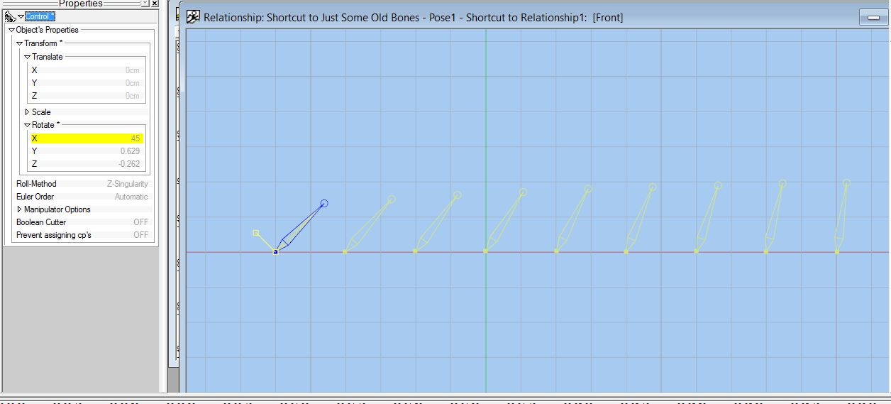
Now, rotate the control bone by 45 and all bones seem to be behaving.
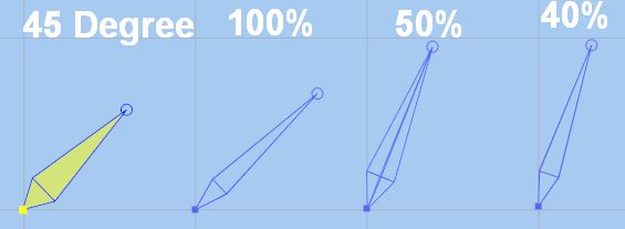
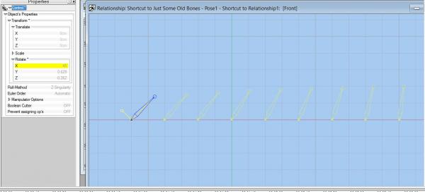
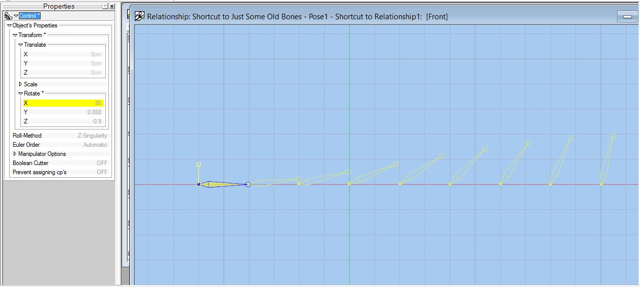
On now to a 90 degree rotation and again everything seems OK. The last bone on the right with a 40% enforcement has rotated slightly less than its neighbour with a 50% enforcement as expected which has rotated to about 45 degrees.
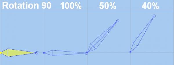
Now when we go above the 90 degree rotation we see that the last bone with 40% enforcement has started to go in reverse (this becomes more pronounced as the enforcement decreases towards 0%). The other bones seem to behaving themselves as expected.
Is there some limit that I missed or am I misunderstanding the whole concept?
Thanks for reading and putting up with this very confused newbie
Oliver
-
All I can say is that it has really changed my approach to model making in AM. I think it should be put up there in lights so that people who are new to the software (like myself) know about it - this means making sure that there is a video on the official website (that just about every newbie watches anyway) to get a toe-up [either under 'hash tutorials' or 'user tutorials']. Once the method is known, that is more than half the battle.
For me, if [period period] brings up the 5-star-patch icon them I'm a happy camper and I'd think that would be the same for the vast majority of people as well.
Thanks again for all your help,
Oliver
-
Hi,
Thanks for all that feedback
DOT DOT or PERIOD PERIOD rules the world.
I've tried it on many things that I had put on hold while trying to get to grips with this problem and they ALL were 'fixed' using the DOT DOT / PERIOD PERIOD method or maybe FULL STOP FULL STOP method
whatever
THANKS ALL
I'd better just cancel the trip to the funny farm as it APPEARS that I still have a couple of marbles left
-
Evening All from windswept, dark and wet West Cork (Ireland),
Maybe it is the weather, but the computer beckoned today and I hauled myself into learning AM again. Nothing difficult but I am again banging the sore head against a harder wall than before.
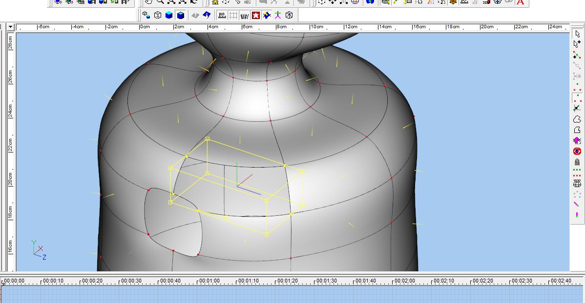
Been trying to cut a hole in a model and had varying levels of success - so much so I decided to get back to basics and see if I could fathom what I was doing wrong. Did a very simple outline, used an 8-sector lathe and formed a simple 3-d model.
Cut a hole in either side and then started filling in 5 point patches. To me (uninitiated) both holes were created exactly the same way.
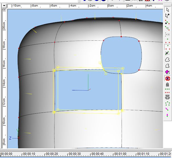
The First Hole: All 5 point patches worked fine but when trying to fill in the last patch - it was a real pain. Selection1, 2 and 3 show the points being selected but the 5-point patch icon is not selectable.
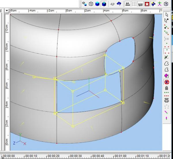

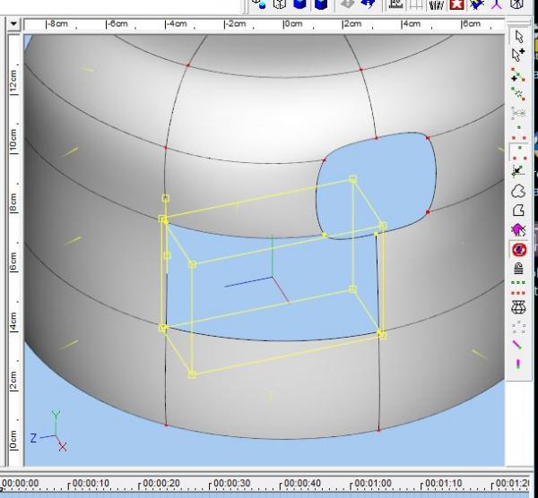
It appeared to be dependant on only selecting points when they were clearly visible and not near the outline graphic of the selection as in 'Selection4'.
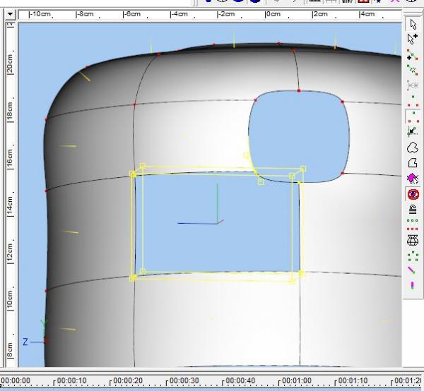
Selection5 shows the final patch created.

So, in this instance, I didn't change the CPs in any way, but it seems that AM is very sensitive to where / how the CPs are selected?
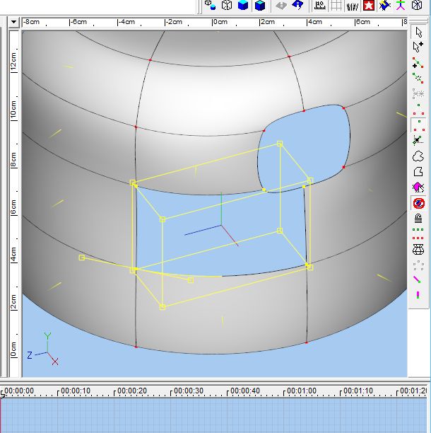
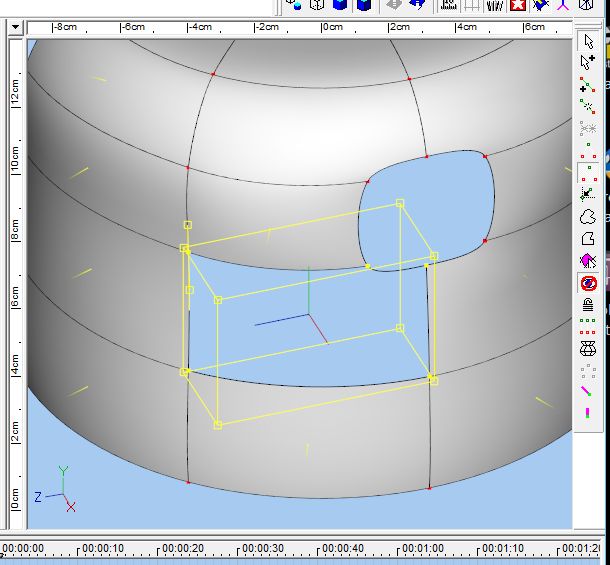
The Second Hole: The first 3 went OK (had a bit of bother with patch 2) but I am now on patch 4 and cannot get the 5-patch icon to become live. This is shown in Selection5 - each of the points that have been selected are clearly visible but still no 5-point selection tool.
Before posting I decided to have one last attempt.
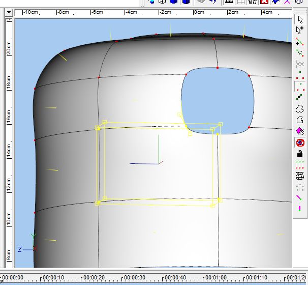
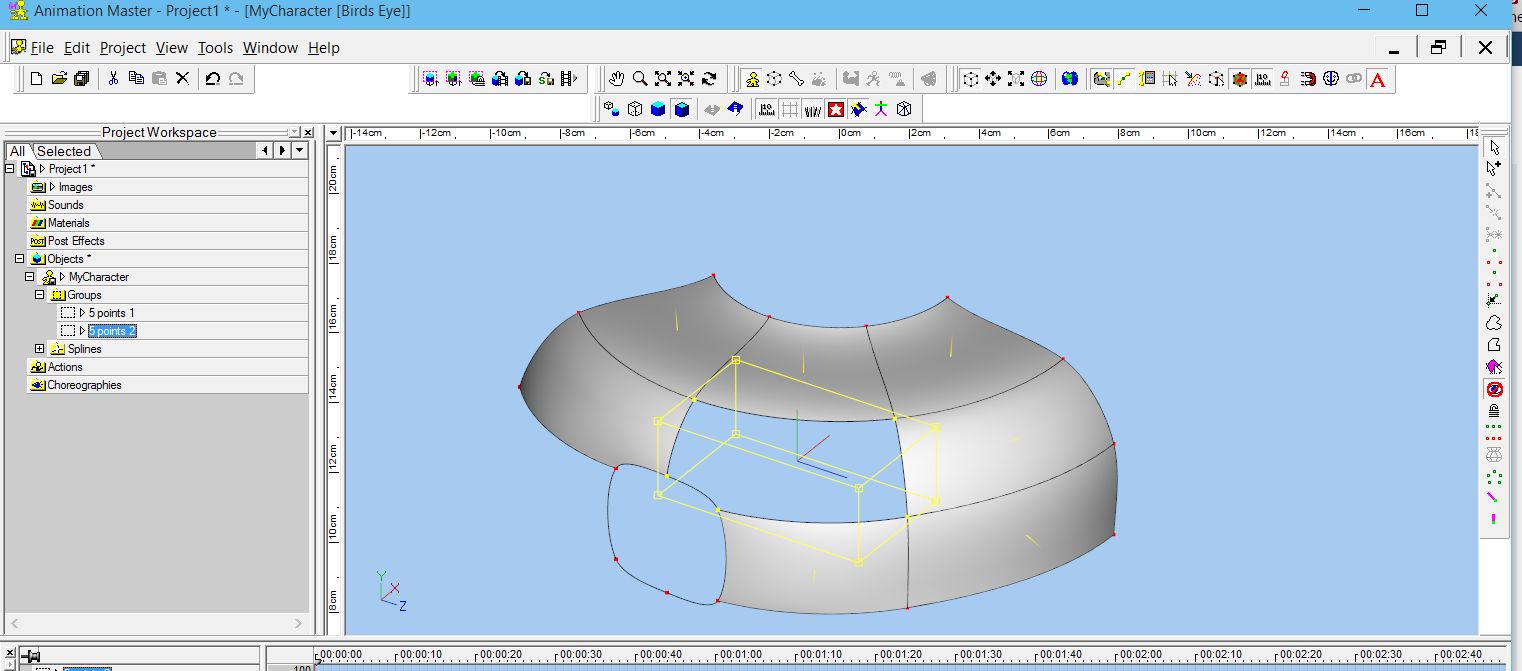
I made a group called '5 points 1' of the group that wouldn't work, I then selected an area around where I wanted to work and hid the rest. Tried selecting the 5CPs again and this time the icon showed - so I named this group '5 points 2'. These are in the attachments '5pt Selection Group1' and 5pt Selection Group2'. Both groups look identical - why does one work and the other not?
Selecting the group '5 points 1' group shows that the 5-pt-patch icon is not enabled.
Selecting the group '5 points 2' group looks identical and now the 5-pt-patch icon is enabled.
Have I missed the plot somewhere and making life unnecessarily difficult for myself - or is it just the cold snap and rain affecting my brain
and if I go to be will everything be right in the world when I wake up?Sorry for being so long-winded
Oliver
-
Hi,
I see now that there is 'more than 1 way to skin the cat'!
Thanks for your files - I'm learning
cheers,
Oliver
-
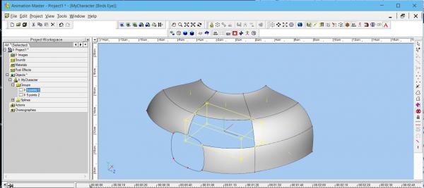
I believe you can just use the lathe tool - no need to cfa first - that is what is causing the problem. Here's a simple example screen capture
Note that I peaked the splines before I hit the lathe
selected only one cp (any cp) - then hit the lathe tool
then I closed the top, bottom holes. Now you can decal the top and bottom with planar decal, and the cylinder part with a cylindrically applied decal
Hi Nancy
So Simple!!! and makes sense once I think back about what I was doing
Tried to like this reply but it seems that I've reached my quota of positive votes for the day???
Thanks,
Oliver
-
Still having difficulty
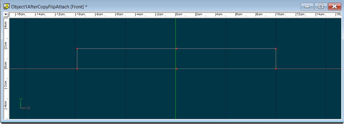
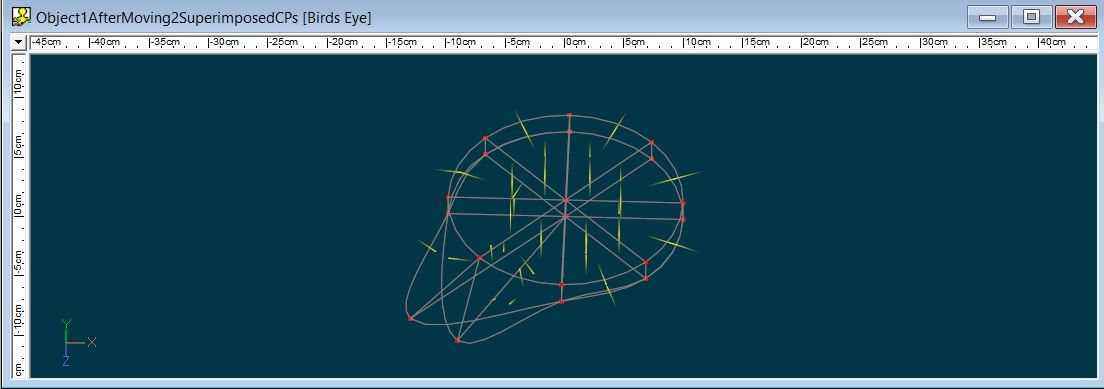
One suggestion was to set the left hand CPs slightly off-centre - which I did, and then did the Copy / flip /Attach
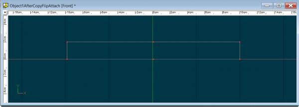
I then did the lathe action
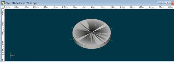
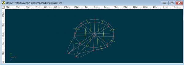
It looks fine, but then I just checked a couple of CPs by grabbing and moving them and I still have extra faces superimposed on each other.
I also saved the object after each procedure which I'm also uploading in case someone can see what I'm doing wrong.
Object1AfterCopyFlipAttach.mdl
Object1AfterMoving2SuperimposedCPs.mdl
The question now is - how do I stop these extra faces being created when I do the lathe operation
Thanks all for your suggestions - maybe I'm not understanding them and/or implementing the suggestions
Cheers and thanks for your help,
Oliver
-
In general it looks like you have internal patches / 2 patches above eachother there...
Could you show a wireframe? Just for testing, you could click on one point on the "poor"-looking patch and drag it away. If you see another one below it, there is the problem.
See you
*Fuchur*
Hi,
You're quite right. I clicked on one of the CPs and there was another one below - in fact there is what looks like another copy below.
Before going any further - I'm heading back to basics and try to work out why I have these copies - thanks for the heads up, great to have something to mull over instead of belting holes in the wall with my head.
Oliver
-
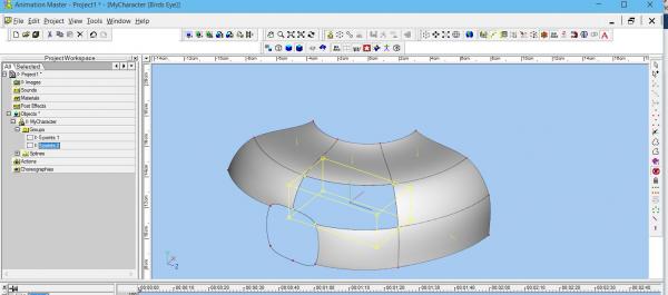
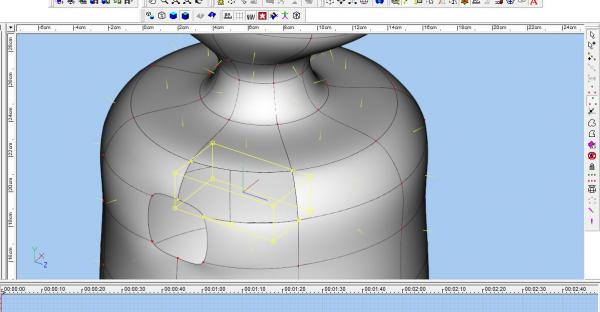
Hi,
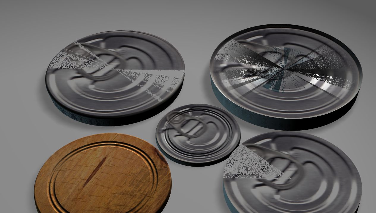
I'm back - and starting at the very beginning. Decided to start with cylinder type models, but the results are not consistent. The problem is with the top surface using planar decals.
Looking at the attached photo you can see 2 poor quality decals and I can't work out what I'm doing wrong
and 2 that are OK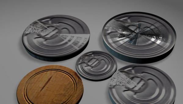
For each, I started with the right hand outline, did the flip/copy/attach and then used the lathe. The breadboard (bottom left) probably had the most complex shape and yet turned out really nice. The only other one which turned out OK is the middle one which was a basic cylinder - nothing complex at all. No doubt I'm making a really basic mistake in the process but I can't work out what I'm doing wrong..
Anyone got any ideas on what I'm doing wrong - or how to work out where the problem is?
Thanks for any assistance,
Oliver
-
Hello All,
Thanks for the suggestions and sorry for being so late in replying and thanking you all - been away and then I lost my password

I've decided that it probably isn't worth the hassle importing from Sketchup, so I'm taking the plunge and starting to venture into the spline world.
Should be interesting.
Maybe in a year or so I'll even understand what everyone is talking about

back to the 'drawing board'
Oliver
-
Hi,
The geriatric is returning to AM after a break of about 5 years. During the interval I've created a big library of models using SketchUp (free version) and there is really only Collada DAE or STL export options available in SketchUp for me. The DAE also has an option to include texture data in the export.
So the question that just about everyone must ask - is there any way of converting DAE to any of the AM import formats (without breaking the bank)?
OR
Is it possible to re-texturise / paint the STL imported model?
Any help will probably allow me keep a bit more of the ever thinning thatch on top of the brain cells,
Cheers,
Oliver


Materials Library (lib) Add New Materials?
in New Users
Posted
Hello Again,
In terms of (2) above, I think I've sorted that one out. I made a copy of 'My Library' and put it into one of my own folders and renamed it as 'MyPersonalLibrary'.
I made a directory in that library and put in some materials.
Within A:M that library is now available in the dropdown list
When I select 'All Libraries' my new one appears as expected
When I select the 'Hash Library1' there is a reference to the folder in my personal library and showing as empty.
The same for 'My Library' which is the library file in Hash V.18
And finally, when I select 'MyPersonalLibrary' it shows my materials folder with materials in it as I would expect.
QUESTION: Is that normal to show folders from 'other libraries' and to show them empty? I'm finding it a little confusing because, in the above example, 'MyMaterials' folder only exists in 'MyPersonalLibrary.lbr' adn not in any other library - or have I missed something?
Confused
Oliver