DJBREIT Posted December 15, 2010 Share Posted December 15, 2010 It has been a long time since I have rigged something more complex then a door or a window. And boy did I forget everything. What I have is an electric train pentagram. (For those who don’t know it is the device to draw power from the over head wires). I did some rigging on it but I am drawing a blank on how to set it up. So the user can raise or lower the pentagram. Since this is going in the Contributors Cue with the GG1 I would like to have it set up with easy of use in mind. Pentagram.mdl Quote Link to comment Share on other sites More sharing options...
Hash Fellow robcat2075 Posted December 15, 2010 Hash Fellow Share Posted December 15, 2010 that moves like two legs opposing each other, with knees sticking out in the middle? Try my "Simplest IK leg" tut in my tuts link. in your case the feet would be at the top and the hips at the bottom. Quote Link to comment Share on other sites More sharing options...
DJBREIT Posted December 15, 2010 Author Share Posted December 15, 2010 Thanks I will give it a try. Quote Link to comment Share on other sites More sharing options...
Hash Fellow robcat2075 Posted December 15, 2010 Hash Fellow Share Posted December 15, 2010 As i see it that thing at the top will be like a foot bone with two IK legs attached to it. Quote Link to comment Share on other sites More sharing options...
DJBREIT Posted December 15, 2010 Author Share Posted December 15, 2010 Slowly but sheerly things are coming back. I have the rig working. I can move the contact plate up and down in place and the rest follows as it should. Now for the details. On the lower bars there is a set of inside cross bars that are off set. These bars are what normally control the rise and lowering of the Pentagram contact plate. What I need to set up is a way to move the bottom ends in and out as the Pentagram rise and lowers. I have tried somethings but I don't know if I am going about it thee right way. The updated model Pentagram.mdl Quote Link to comment Share on other sites More sharing options...
Hash Fellow robcat2075 Posted December 16, 2010 Hash Fellow Share Posted December 16, 2010 I'm not really clear on what the mechanical connections are there Quote Link to comment Share on other sites More sharing options...
Hash Fellow robcat2075 Posted December 16, 2010 Hash Fellow Share Posted December 16, 2010 I think I see how it works, now. Hmmm... that's a poser. Quote Link to comment Share on other sites More sharing options...
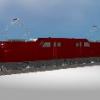
DJBREIT Posted December 16, 2010 Author Share Posted December 16, 2010 I hope the pictures is a lot clear. I have add a slot where the bar moves in and out Quote Link to comment Share on other sites More sharing options...
Hash Fellow robcat2075 Posted December 16, 2010 Hash Fellow Share Posted December 16, 2010 that arm that's by "pulls in/push back" is a challenge. Here's a cheater solution: (See PRJ) Outer Arm and Upper Arm are like an IK leg constrained to the Foot at the top Phantom Arm and Inner Arm are an IK leg constrained to Upper Arm Phantom Arm is so long that the arc it carries Inner Arm on resembles a straight line for this limited case. Phantom Arm seems to get stuck around its original modeled position so I modeled the structure so that Phantom arm is never near that in normal use. PentagramRig04.prj Pentagram.mov Quote Link to comment Share on other sites More sharing options...
DJBREIT Posted December 16, 2010 Author Share Posted December 16, 2010 Yes it seem I have came up with the same set up. Mine was comming from the bottom. it a little buggy. I think I may have come up with something. PentagramRig04.prj Quote Link to comment Share on other sites More sharing options...
DJBREIT Posted December 17, 2010 Author Share Posted December 17, 2010 After adding a constraint or two more I was able to get it to work with out any problem. I would have a video but the forum dose not like avi so I'm doing a QuickTime video. I will post it tomorrow. Quote Link to comment Share on other sites More sharing options...
*A:M User* Shelton Posted December 17, 2010 *A:M User* Share Posted December 17, 2010 Nice gg model. Are you a railroader as well? Steve Quote Link to comment Share on other sites More sharing options...
DJBREIT Posted December 17, 2010 Author Share Posted December 17, 2010 Nice gg model. Are you a railroader as well? Years ago I use to collect but it got pretty pricey. Especially if you collect “O” gauge GG1_p..mov Only one small problem. When the contact plate is raised and lowered in an action the lower inner arm wobbles as it moves forward and backswords. Dose anyone know how to lessen this wobble. Pentagram.mdl Next idem. Setting up the truck/wheels and couplers so they can track a path on a set of "S" curve track. And not having the wheels jumps the tracks. And to make it easy to hook up to other cars. Dose anyone know if someone made a rig for this. I have some ideas and have rig the trucks with some basic bones but I would like to see if some one has already done this in the past. And save me some time a guess work. GG1_Truck_A.mdl Quote Link to comment Share on other sites More sharing options...
Hash Fellow robcat2075 Posted December 17, 2010 Hash Fellow Share Posted December 17, 2010 Next idem. Setting up the truck/wheels and couplers so they can track a path on a set of "S" curve track. And not having the wheels jumps the tracks. And to make it easy to hook up to other cars. Dose anyone know if someone made a rig for this. It's complex because there are so many interacting points of contact, way beyond what a typical arm or leg has to deal with. In the back of my mind i can imagine modeling proxy wheels and an undercarriage in cloth and letting them seek their proper location on the rails and then constraining the real model to that proxy. I know it could work, but like all cloth scenarios much testing would be required. Quote Link to comment Share on other sites More sharing options...
DJBREIT Posted December 18, 2010 Author Share Posted December 18, 2010 After a lot of testing and rigging. It seems it maybe best to let the end user set the model up per scene. Since there is no constraint to allow bones to be pulled along a path. Quote Link to comment Share on other sites More sharing options...
itsjustme Posted December 18, 2010 Share Posted December 18, 2010 After a lot of testing and rigging. It seems it maybe best to let the end user set the model up per scene. Since there is no constraint to allow bones to be pulled along a path. A path constraint didn't work? Quote Link to comment Share on other sites More sharing options...
Admin Rodney Posted December 18, 2010 Admin Share Posted December 18, 2010 Since there is no constraint to allow bones to be pulled along a path. But isn't that what a Path Constraint is for? The pulling force automatically pulls the bone down the path at a constant rate unless the User sets the Ease to a specific percentage. A pushing force can be set up by reversing the percentage. Quote Link to comment Share on other sites More sharing options...
Hash Fellow robcat2075 Posted December 18, 2010 Hash Fellow Share Posted December 18, 2010 Since there is no constraint to allow bones to be pulled along a path. But isn't that what a Path Constraint is for? The pulling force automatically pulls the bone down the path at a constant rate unless the User sets the Ease to a specific percentage. A pushing force can be set up by reversing the percentage. A Path constraint is always driven by ease, the default 0-100 ease if you don't set it. But an object on a path constraint won't react to an external force. The other problem, for a train car, is that it has leading and trailing wheels and the path distance between them will be greater on a curve than when they are on a straight line. I suppose a new path constraint could be made that allows a bone to freely slide along a path in response to some other action upon it. Possible. Quote Link to comment Share on other sites More sharing options...
DJBREIT Posted December 18, 2010 Author Share Posted December 18, 2010 A path constraint didn't work? But isn't that what a Path Constraint is for? The pulling force automatically pulls the bone down the path at a constant rate unless the User sets the Ease to a specific percentage. A pushing force can be set up by reversing the percentage. In this case I only need the first bone to be set with Ease. But the rest of the bones only need to stay on the path. It would be like pulling a chain down a path where all the links stay on the path no matter what you set the speed/ease on the first bone. And since there is no option for this that I know of. It would be easer to leave the final setup with the user. Any rig I can come up with would have the same inter face problem. Quote Link to comment Share on other sites More sharing options...
Recommended Posts
Join the conversation
You are posting as a guest. If you have an account, sign in now to post with your account.
Note: Your post will require moderator approval before it will be visible.